® CCS-100 ELECTR O NIC CRUISE CO NTR OL ELECTRO CONTR NTROL INST ALLA TI ON M ANUAL INSTALLA ALLATI TIO MANUAL
INDEX Page 1. Cruise Control Installation: ..................................................... 1 Parts List ........................................................................... 2 Throttle Connections......................................................... 3 Wiring ............................................................................... 4 2. Control Switch Installation...................................................... 8 Troubleshooting ...................................................
HOW THE CRUISE WORKS The Cruise Module makes "decisions" based upon speed,tachometer, and brake signal information. The control circuit interprets digital speed information from the car's engine control module (VSS) or Magnet Kit and ignition coil output. Brake information comes from the red and purple wires connected to the vehicle's brake switch. Disengagement and no-engagement decisions are based on the monitored information. An integral part of the cruise is the 'over rev.' protection circuit.
PARTS LIST Servo Assembly (1) M6 external tooth star washer (3) Dash Mounted control switch (1) ACC ON OFF CRUISE CONTROL AUDIOVOX -1- -2- Tie Straps ( 10 ) 1/2" rubber bulkhead grommet (1) RES SET CST -3- -4- -5- Convoluted tubing (1) Vacuum hose reducing nipple (1) Assorted Vacuum T - Connectors Vacuum Hose - Short (1) Vacuum Hose - Long (1) -6- -7- -8- -9- - 10 - Main Wiring Harness (1) Fused wire with switch connector (1) Scotch lock connectors (4) Female T- tap terminal (1)
PROGRAMMING THE SERVO ASSEMBLY To ensure that the cruise control operates smoothly and safely in your vehicle, the servo assembly must be programmed. In order to properly program the servo assembly, you will need to know the number of cylinders, the type of transmission (manual or automatic), if your vehicle is equipped with a Vehicle Speed Sensor (VSS), and if so, the number of Pulses Per Mile ( PPM ), also if the cruise control switch is the open or closed circuit style.
UNDER HOOD INSTALLATION Connecting the Cruise Control Cable to the Throttle NOTE: Prior to attaching servo cable to throttle, locate an accessible area to mount the cruise control servo, but do not mount it. Leave the servo in this area (unmounted) and route cable to throttle attachment area. CAUTION: Attach the cruise control cable so that it parallels the existing throttle cable as nearly as possible. Choose a mounting method from the figures below: FIG.
FIG. 8 FIG. 9 FLEX CABLE CONDUIT MOUNTING ALTERNATE FLEX CABLE MOUNTING TECHNIQUE 4"R Min. Select a location which provides 1-3/4" travel to match actuator. Mounting Bracket used to lock down carburetor end of flexible cable (bend as required). Tube Clamp (#17) Parallel Throttle Cable Clamps (#18) used to lock cable end to existing throttle housing FIG. 10 ALTERNATE FLEX CABLE MOUNTING TECHNIQUE FIG.
CAUTION ! ATTACH THE CRUISE CONTROL CABLE SO THAT IT PARALLELS THE EXISTING THROTTLE CABLE AS NEARLY AS POSSIBLE. WARNING ! AFTER ATTACHING THE CRUISE CONTROL CABLE TO THE VEHICLE’S THROTTLE, OPERATE THE THROTTLE MANUALLY ( FULL TRAVEL ) FROM BOTH UNDER HOOD AND ACCELERATOR PEDAL TO BE ABSOLUTELY SURE THAT NONE OF THE CABLE ATTACHMENT COMPONENTS OR BEAD CHAIN CAN RESTRICT OR INTERFERE WITH THE NORMAL THROTTLE OPERATION. Mounting the Servo Assembly 1.
Routing the Main Wiring Harness 1. Locate your vehicle by make, model, and engine size in the included Reference Manual in order to identify the location of the VSS and Tach connection locations. If your make and model cannot be located, then the Magnet Kit must be installed. Follow the installation instructions included in this manual. In all cases, you will need to route the Brown, Green , Purple, Yellow, and Red wires through the bulkhead to the passenger compartment of the vehicle.
5. Locate the fused wire with switch connector included in the kit, and load the Brown, Green, and Yellow wires from the main harness into the 4 pin switch connector. Be sure to load the wires according to the color coded label on the connector, and press the terminals in fully until a click is heard. 6. Orange Wire : Connect the Orange wire from the fuseholder to a wire in the vehicle that shows + 12 VDC when the ignition key is switched On and 0 VDC while cranking and when the key is switched OFF.
DASH BOARD TEMPLATE Figure 1 Drill 1/4" Dia. holes, (2 places). Carefully cut-out along dotted lines and place on selected area. Use a file or razor knife to remove the material between the 2 holes.
ROAD TESTING THE CRUISE CONTROL Be sure to fully test all functions of your new cruise control on a level surface away from predestrian and vehicle traffic. While travelling 35 M.P.H. turn switch on , then press Set button. Unit will engage when Set button is released. To disengage, tap on brake or turn switch off - cruise will disengage. Follow same procedure at 45 M.P.H. and at 55 M.P.H. If unit is inoperative, open cover on cruise and look at the L.E.D. Press Set button, L.E.D. should light.
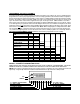
TROUBLE SHOOTING WIRING - 10 PIN CONNECTOR Note : If the brown, green, or yellow wires do not test properly, proceed immediately to the testing of the 4 pin control switch testing. POS WIRE COLOR FUNCTION 9 Black Always continuity to ground 3 Red Always + 12 VDC 1 Brown + 12 VDC with Ignition switch and cruise control switch ON. O VDC with Ignition switch or cruise control switch OFF. 4 Purple + 12 VDC when the brake pedal is pressed. 0 VDC when the brake pedal is released.
M AGNET KIT INST ALLA TI ON INSTALLA ALLATI TIO MAGNET AND SPEED SENSOR COIL INSTALLATION The magnets, along with the speed sensor coil provide pulses to calculate road speed for the cruise control. When the drive shaft rotates, the magnets attached to it move by the speed sensor coil. This generates electrical pulses which are monitored by the cruise control. This installation will require access to the vehicles drive shaft/axle.
Step 6: While rotating the shaft, carefully snap one wire into one set of magnet slots. Loosely wrap the wire to hold it in place. Snap the second wire into the remaining slots making sure the ends are nearly opposite the first wire, as shown in Figure 4 or 11. Step 7: Carefully pull wires tight, and twist with a pair of pliers, pulling down as you twist to avoid breaking the wire. Now take the loose ends and wrap through the opposite wire, and twisting as above to remove any excess slack, see Figure 4.
INSTALLATION - REAR WHEEL DRIVE VEHICLES DRILL 3/16" DIA HOLES IN FLOOR PAN OF VEHICLE EXISTING CABLE OR BRACKET ON VEHICLE DRIVE SHAFT CABLE TIE PULL TIGHT 12" MAX.
INSTALLATION - FRONT WHEEL DRIVE VEHICLES TRANSMISSION AXLE HOUSING DRILL OR FILE BRACKET TO FIT EXISTING BOLT 3/8" RIGHT FRONT AXLE ONLY WIRES AND MAGNET Figure 6 DIA.
® 12 MONTH LIMITED WARRANTY Applies to automotive speed controls. AUDIOVOX CORPORATION (the Company) warrants to the original retail purchaser of this product that should this product or any part thereof, under normal use and conditions, be proven defective in material or workmanship within 12 months from the date of original purchase, such defect(s) will be repaired or replaced with new or reconditioned product (at the Company's option) without charge for parts and repair labor.
Audiovox Corp., 150 Marcus Blvd., N.Y. 11788 Form No.