Wireless 4.5” LCD Display System Model: ACA450 Installation/User Manual Features: • 4.5" TFT Color LCD Display • On Screen Display Function • 2.
TABLE OF CONTENTS Warnings 2 Product Description 3 Packing List 3 Installation Instructions 4 Controls and Indicators 6 Specifications 7 Maintenance 8 Troubleshooting 8 1
Warnings The product is intended to assist in safe driving and to allow the driver to have a broader rearview while the vehicle is in reverse. You, as the driver, are solely responsible for the safe operation of your vehicle and the safety of your passengers according to your local traffic regulations. Do not use any features of this system to the extent it distracts you from safe driving. Your first priority while driving should always be the safe operation of your vehicle.
Product Description This Wireless Backup Camera/Monitor Package is designed to assist the driver by providing a clear and wide image of the area behind the vehicle whenever the vehicle is shifted into reverse. Never rely solely on this product to ensure the area is clear of children and/or obstructions. Use your monitor and look both ways. This product is not intended to replace existing safety procedures, but rather to add an additional safety tool for your vehicle.
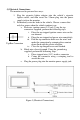
Installation Instructions 4-Bolt Amps Style Mount T-slot for Mounting Figure 2 (Mounting the Monitor) NOTE: Amps Style Mount is an industry standard 4-bolt pattern for assorted style mounts available at many retailers. Use caution when installing bolts, as bolts that are too long will damage the monitor. (1) Installing the Visor Clip (mounting bracket) a) Slide the Visor Clip all the way onto the T-slot on the back of the monitor, as shown in figure 2. b) Slide the Visor Clip over the sun visor.
(3) Electrical Connections: The monitor can be powered two ways: 1. Plug the cigarette lighter adapter into the vehicle’s cigarette lighter socket, and then insert the 2.5mm plug into the power supply jack on the monitor. 2. Permanently wire the leads to the vehicle. Choose a source that only has power when the vehicle ignition is on. a. Red wire: ignition source +12 volt. Using the tap connectors supplied, perform the following steps: i. Place the un-stripped ignition source wire on the run channel ii.
Controls and Indicators D A E B C Figure 2 Back Side of Monitor Figure 2 illustrates the controls and indicators on the back side of the ACA450 Monitor: A: Menu Key-shows on screen displays B: “+” Volume Adjustment Key C: “-” Volume Adjustment Key D: Four Position/Channel Receiver Frequency Switch NOTE: Position switch should be in the #1 position. Monitor can receive 4 different frequencies, as noted in specifications, and can receive 4 separate camera signals (optional).
Specifications General Power Supply Power Consumption Current Draw Operating Temperature Range DC12V <6W <400 mA 0 to 50 Display System Screen Brightness Contrast Ratio Backlight Life Resolution Video Format Display Format 4.5” TFT Color LCD 400 cd/ 150:1 10000 hours 960×234 NTSC/PAL 16 : 9 Wireless Reception System Operating Frequency Selectable Channel Quantity 2.
Though your monitor requires little care, you will still need to maintain its condition and performance by following the guidelines below. • Keep your system away from excessive moisture, extreme heat or cold. • Keep liquids away from the display. • Occasionally clean the surface of the monitor with a soft cloth moistened with water or glass cleaner. Troubleshooting Symptoms Solutions The Monitor is not on after the vehicle is started and the vehicle is in reverse 1.
9
© 2007 Audiovox Electronics Corp., 150 Marcus Blvd., Hauppauge, N.Y.