4 Sensor Backup Obstacle Sensing System Model: ACAB104 Installation Manual 0° Features: • • • • • • • Four reversing sensors detect obstacles between 1- 7 feet Includes 0°, 5°, and 10° angle sensor sleeves to fit most bumpers Activates only when vehicle is in reverse Will not drain battery or void factory warranty Includes speaker/buzzer with 3 settings - high, low, and off Four detection zones give the following warnings: 1 = slow beep within 5-7 feet 2 = medium beep within 3-5 feet 3 = fast beep withi
TABLE OF CONTENTS Warnings....................................................................................2 Product Description ...................................................................3 Packing List ...............................................................................3 Installation Instructions .............................................................4 Mounting the Sensors .......................................................4 Installing the Power Harness .....................
Warnings This product is intended to assist in safe driving by signaling the driver of obstacles behind the vehicle while the vehicle is in reverse. You, as the driver, are solely responsible for the safe operation of your vehicle and the safety of your passengers according to your local traffic regulations. Do not use any features of this system to the extent it distracts you from safe driving. Your first priority while driving should always be the safe operation of your vehicle.
Product Description This 4 Sensor Backup Obstacle Scanning System is designed to assist the driver by providing an alert when an object is behind the vehicle whenever the vehicle is shifted into reverse. Never rely solely on this product to ensure the area is clear of children and/or obstructions. This product is not intended to replace existing safety procedures, but rather to add an additional safety tool for your vehicle.
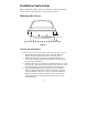
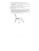
Installation Instructions Before installing this product, take time to familiarize yourself with the items in the box and use the packing list to verify all parts are present. Mounting the Sensors 6-12" 6-12" Equal Spacing of Sensors 19.5-27.5" Figure 1 Marking and Drilling Holes 1. Mark the locations of the sensors on the rear bumper using a grease pencil. a. Identify the sensors height on the bumper and mark. The sensor height should be between 19.5” and 27.5” from the ground. b.
2. Choose one of the following mounting methods for your vehicle a. Use the sensor sleeves provided to compensate for contours in the vehicles bumper. b. If the surface is 90- 95 degrees perpendicular to the ground, install the sensors directly in the bumper (see Figure3). 3. Before drilling the holes, use a center punch to make a dimple on the bumper to prevent the drill from slipping from the intended mark. 4. Drill the sensor holes. o When using the sensor sleeves, use a 28mm hole saw (part# AS28MMHS).
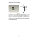
Choosing the Correct Sensor Sleeve A rro wh ea d u pwa rd 90 -9 5 Figure 3 The position of the sensors must be between 90°-95° perpendicular to the ground (Figure 3). Due to different contours in vehicle bumpers 3 different sensor sleeve angles (0°, 5°, & 10°) have been included with this system to aid in the proper installation of the sensors at the proper angle to the road.
Installing the Sensor Sleeve and Sensors NOTE: When installing the sensors into the sensor sleeves, push on the outer ring of the sensor only. Never push on the center of the sensor.. 1. Press the pre-selected sleeve into a 28mm hole in the bumper, making sure the thinner edge of the sensor sleeve is at the top of the hole. 2. Run the sensor wires through the sensor sleeves in the bumper. 3. Press on the outer ring of the sensor and push until the sensor is flush with the sensor sleeve.
Installing the Power Harness Tap/Run Connection 1. 2. Wire the Power Harness to the vehicle’s reverse lamp. a) Locate the reverse lamp in the tail light assembly. Using the tap connector supplied, perform the following steps: i. Place the un-stripped positive lead wire on the run channel. ii. Insert the un-stripped red power wire completely. iii. Fold the tap connector back over the wires and make the connection by crimping the u-contact down flush with the plastic insulator. iv.
Mounting the Speaker The speaker has three volume settings: Off, Hi, and Low. Since the speaker can be adjusted as needed, you should mount the speaker in an accessible location in the interior. 1. Route the wires for the speaker to the area where you will install the control module. Make sure they will not be pinched by the panel or moving parts. 2. Clean the mounting location to ensure good adhesion.
Mounting the Control Module Determine a dry place inside the vehicle (out of the way) to mount the control module (e.g., behind an inner body panel), making sure that all wiring will reach the intended location. 1. Plug the sensor wires, speaker and power harness into the control module before mounting. The sensor must be plugged into the corresponding socket (see Figure 4). The control module is pre-fitted with Velcro for mounting. 2.
Specifications Power Supply Current Draw Detecting Distance Sensor Cable Length Control Box Size Operating Temperature Range DC12V <180mA 1 to 7 ft 23 ft 4.125”x 3”x .830” -40°F~ 176°F Maintenance Though your backup system requires minimum care, you should maintain its condition and performance using the following the guidelines: • Keep the control box away from moisture, extreme heat or cold. • Keep the sensors free from snow, ice, and debris.
12
© 2008 Audiovox Electronics Corp., 150 Marcus Blvd., Hauppauge, N.Y.