® OWNER'S MANU AL MANUAL AND INST ALLA TION GUIDE INSTALLA ALLATION ACD-32A ACD-32A DETACHABLEFRONTPANEL ELECTRONICALLY-TUNEDAM/FM/MPXRADIO WITHCOMPACTDISCPLAYER ANDQUARTZCLOCK Released 1-28-98. (Output Power was 50 watts).
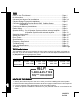
INDEX How To Use This Manual ....................................................................... Page 1 Kit Information ........................................................................................ Page 2 Universal and Import Car Installations ................................................... Page 3,4 Chrysler-Dodge-Plymouth Installations .................................................. Page 5 Chevrolet-Oldsmobile-Pontiac-Buick-GMC Cadillac-Saturn Installations ...........................
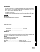
KITINFORMATION 1. The years shown in the Kit Listing below are approximate. Always check the application chart at your retail store to find information on your specific make, model and year of vehicle. If a kit is required, read the description on the kit you intend to purchase to make sure it applies to your vehicle. If you have any doubts or questions, call our toll-free "HELP" line. 2. The kits shown below are Audiovox kits.
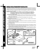
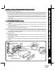
UNIVERSAL INSTALLATION ANDIMPORTCAR INSTALLATION UNIVERSALINSTALLATIONANDIMPORTCARINSTALLATION This installation is designed for cars, trucks, vans, and boats that have an existing radio opening that is no larger than the size shown on the template provided (182mm wide x 53mm high). If the opening is smaller than required, you can use a file to enlarge it to match the template, using the slots on the template as a guide.
4.WiretheRadiototheVehicle'sWiring: A. Place radio in front of dashboard opening so that wiring can be brought through the mounting sleeve. B. Carefully follow the diagrams on pages 8 and 9 or 10 to wire the radio, making certain all connections are secure and insulated with wire nuts or electrical tape to insure proper operation of the unit. C. After completing the wiring, re-attach the front panel to the chassis and turn the unit on to confirm operation (ignition switch must be "on").
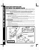
CHRYSLER-DODGE-PLYMOUTH INSTALLATION CHRYSLER-DODGE-PLYMOUTHINSTALLATION AllU.S.MadeCars,Trucks,andVansBuiltSince1974 Important-This radio cannot be installed in any U.S. made Chrysler, Dodge, or Plymouth without an installation kit. Refer to Kit Listings on page 2 for the required kit. Complete kit installation is explained in the instructions included with the kit. CAUTION: 1. DO NOT CUT OR FILE THE OPENING TO THE OUTER EDGES OF THE TEMPLATE! 2.
Important-This radio cannot be installed in any "GM" vehicle without an installation kit. Refer to Kit Listings on page 2 for the required kit. Complete kit installation is explained in the instructions included with kit. This radio cannot be installed in GM vehicles built before 1982. CAUTION: 1. DO NOT CUT OR FILE THE OPENING TO THE OUTER EDGES OF THE TEMPLATE! 2. FOR PROPER OPERATION OF THE CD PLAYER, THE CHASSIS MUST BE WITHIN 20° OF HORIZONTAL. MAKE SURE THE UNIT IS MOUNTED WITHIN THIS LIMITATION. 1.
FORD-LINCOLN-MERCURY INSTALLATION FORD-LINCOLN-MERCURYINSTALLATION AllU.S.MadeCars,Trucks,andVansBuiltSince1985 Important-Measure the size of your existing radio opening. If it is no larger than the size shown on the template provided, you can install the radio as explained on pages 3 and 4. If the opening is larger, you must use a kit. See Kit Listing on page 2. This radio cannot be installed in Ford cars built prior to 1985. CAUTION: 1.
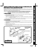
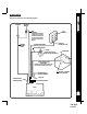
REFERTOPAGE9OR10FORSPEAKERWIRING ANTENNA AUTOMATIC ANTENNA CAR FUSEBLOCK PINK IMPORTANT RADIO WIRING RADIOWIRING THEPINKWIRECANBEUSED TOREMOTELYACTIVATEAN AUTOMATICANTENNAORAN EXTERNALAMPLIFIER(SEE ANTENNA OR AMPLIFIER MANUAL) EXISTING ANTENNA CABLE "RADIO"OR "ACCESSORY"FUSE ORANGEw/WHITESTRIPE BLACKw/WHITESTRIPE SCREW METALPARTOFDASH (DRILLHOLEIFNECESSARY) CARBATTERY GREENw/WHITESTRIPE IMPORTANT THISWIREMUSTBECONNECTEDASSHOWN ORRADIOWILLNOTOPERATEPROPERLY SEEPAGES9AND10 FORSPEAKERWIRING POSI
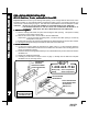
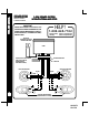
SPEAKERWIRING SPEAKER WIRING REFERTOPAGE8 FORRADIOWIRING 2 OR 4 SPEAKER SYSTEMS WITHOUTEXTERNALAMPLIFIER HELP! IMPORTANT WHENUNITISWIREDTOEITHERA2OR4 SPEAKERSYSTEMASSHOWNBELOW,THE FADERCONTROLMUSTBESETTOTHEFULL FRONTPOSITION("L-R"ONDISPLAYPANEL) ANDNOTUSED.
REFERTOPAGE8 FORRADIOWIRING 4 SPEAKER SYSTEMS WITH OPTIONALEXTERNALAMPLIFIER IMPORTANT WHENUNITISWIREDTOA4SPEAKERSYSTEMASSHOWNBELOW, THEFADERCONTROLONTHERADIOWILLBEOPERABLE.
OPERATING INSTRUCTIONS OPERATING INSTRUCTIONS 2 dl 1 3 u b ACD-32A bl cl n bm b c p co m d 9 u c bt 1 POWER OFF BUTTON Press this button to turn the unit off. Use the Radio On/Band Selector button or CD Mode Selector to turn the unit on. cl bl 2 VOLUME / LEVEL CONTROLS To increase the volume level, press the + button. The volume will increase and the level will be shown by the bars under the “VOL” indication on the display panel. To increase the volume quickly, keep the button pressed.
6 LEFT/RIGHT BALANCE CONTROL To adjust the left-right speaker balance, first select the Balance mode by pressing the Select button until the “BAL” indication appears on the display panel. Within 5 seconds of choosing the Balance mode, press the - button of the Level Control to adjust the stereo balance to the left channel speakers or the + button of the control to adjust it to the right channel speakers.
OPERATING INSTRUCTIONS bq AUTO-STORETUNING(AS) PRE-SET SCAN TUNING (PS) Press this button momentarily to scan the 6 stations in the pre-set memories of the band in use. The unit will stop at each pre-set station for 5 seconds before continuing to the next pre-set station (the pre-set number on the display panel will flash during Pre-Set Scan operation). Press the button again momentarily to stop Pre-Set Scan operation and remain on the selected frequency.
Press this button to turn on the unit if a disc is already loaded in the player. When listening to radio with a disc loaded in the unit ( DISC on the display panel), press this button to return to disc play mode from the point at which play was stopped. cm FORWARD TRACK SELECT ( ) cn BACKWARD TRACK SELECT ( ) The Track Select functions are used to quickly access the beginning of a particular track.
OPERATING INSTRUCTIONS 3. If there is a malfunction of any of the switches on the unit or of the CD player, pressing the ReSet button may clear the system and return to normal operation. dn FRONT PANEL RELEASE KNOB This knob is used to release the mechanism that holds the front panel to the chassis. To detach the front panel, slide the button to the right so that the left side of the panel is released. Grasp the released side and pull it off of the chassis.
Size: 7" W x 2" H x 6-1/4" D 178 mm x 50 mm x 160 mm Operating Voltage: 12 volts DC, negative ground Output Power: 64 watts maximum Output Wiring: Floating-ground type designed for 2 speaker use. May also be used with 4 speakers. RCA low-level outputs. Output Impedance: Compatible with 4-8 ohm speakers. Low-Level Output: 500 mv. Tuning Range: AM: 530-1,720 KHz. (10 KHz. step) 522-1,620 KHz. ( 9 KHz. step) FM: 87.5-107.9 MHz. (200 KHz. step) 87.5-108.0 MHz. (50 KHz.
TROUBLESHOOTING TROUBLESHOOTING PROBLEM Unit completely inoperative no lights, no sound PROBABLE CAUSE CHECK FOLLOWING Incorrect power connection Orange/White stripe wire to +12V ACC.
The radio section of your new sound system does not require any maintenance. We recommend you keep this manual for reference on the many features found in this unit as well as how to set the clock. The compact disc player section also requires no routine maintenance, but proper understanding of its use and handling will help you obtain maximum enjoyment of its capabilities. The following points should be observed: When cleaning the interior of the vehicle, do not get water or cleaning fluids on the unit.
12 MONTH LIMITED WARRANTY Applies to In-dash radios, radio/tape player and radio/CD player combinations, and CD Changers.