
Installation Guide

3
1.
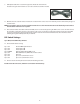
The navigation module can be located behind,under, or to either side of the radio depending on space available.
Determine your exact mounting location to insure you route your wires correctly.
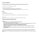
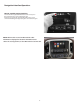
2. Using the supplied T-harness power cable, disconnect the matching
cable from the rear of the main radio unit. Plug the T-harness in
the radio and the factory harness into the T-harness. (Yellow arrow).
3.
Plug the supplied LVDS cable in to the radio screen and the
factory cable into the LVDS t-harness cable from the nav unit.
Connect the LVDS cable to the Nav module.
Cadillac CUE system Shown above
NOTE: The Buick, GMC radio panel will look dierent than the picture above but the connections are the same.
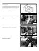
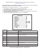
4. Connect the CAN module to the power harness connection.
5. Connect the CAN to Nav interface cable to the main Nav module as shown in the wiring diagram.
6. The system utilizes either the center front speaker in the dash or an included external
speaker for easier installation or for vehicles that do not have a center channel speaker.
The Nav system will mute the radio audio in that speaker only when giving directions.
NOTE: The left dash speaker will also work if no center speaker is available.
To install using the factory speaker, remove the center channel speaker from the dash,
route the included speaker harness to the speaker location. Connect the supplied harness
to the speaker and the OEM wiring to the other harness connector. Route the wire to the
module and connect.
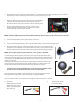
If using the included External speaker pick a location that is not obstructed and can be
heard easily by the driver. Remove the tape backing from the rear of the speaker and
attach to the mounting location. Route the wire to the module and connect.
• If needed or for custom installation this can be wired to any standard 4 ohm
speaker. The Green and Gray colored wires are the audio output.
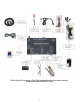
The Nav module has the ability to add a backup camera and 2 AV inputs. The module
will support the factory backup camera if the vehicle is equipped with this.
If you are adding a camera or aux inputs, use the supplied cables and connect as needed.
7. Aux Video: 8. Aux Video: Aux Audio:
Red: Backup Camera Input See attached labels
Yellow: Aux 1 Video Input
White: Aux 2 Video Input
Gray: Not used