Model APS-55 Installation Manual 3 Channel Remote Start / Keyless Entry System Installation Instructions This Unit Is Intended For Installation In Vehicles With 12 Volt Negative Ground Electrical Systems, Gasoline or Diesel With True Tach Reference And Automatic Transmissions Only.
The APS-55 Remote Start/Keyless Entry System is designed to be used with Automatic Transmission Vehicles Only! The unit provides wait to start input for glow plug pre-heat which will be used for all diesel applications. If this wire is not connected, then the unit will remain in the Gasoline mode setting which will crank the car when the RF signal is received with no delay.
IMPORTANT! DO NOT PLUG THE SIX PIN MAIN POWER HARNESS OR THE MULTI PIN INPUT / OUTPUT HARNESS INTO THE CONTROL MODULE UNTIL ALL CONNECTIONS TO THE VEHICLE HAVE BEEN MADE. AFTER SELECTING YOUR TARGET WIRES AS DEFINED BELOW, DISCONNECT THE NEGATIVE BATTERY CABLE FROM THE VEHICLE BATTERY PRIOR TO MAKING ANY CONNECTIONS.
SEE NEUTRAL START SAFETY TEST FOR FURTHER DETAILS. BLUE Wire: Ignition 1 Output Connect this wire to the ignition 1 wire from the ignition switch. This wire will show +12 volts when the ignition key is turned to the to the "ON" or "RUN" and the "START" or CRANK" positions and will have 0 volts when the key is turned to the "OFF" and "ACCESSORY" positions. For Diesel Applications, this wire must be connected to the ignition circuit that powers the glow plugs if the vehicle requires glow plug pre-heating.
WIRING CONNECTIONS: 12 Pin Input / Output Harness Black Wire: Chassis Ground Source Connect the Black wire to a known vehicle ground source or to a solid clean metal part of the chassis. Be certain to remove any paint or grease and secure this wire with a self tapping screw and ring terminal. BLACK w/WHITE Tracer Wire: Control Switch The Black w/ White tracer wire provides ON-OFF control of the Remote Starter.
the Brown w/ Black trace wire to the output of the brake light switch. If the brake light switch in the vehicle switches ground, do not use the Brown w/ Black wire; see Grey w/ Black tracer wire. Brake Switch Positive Shutdown Detail YELLOW w/ BLACK Tracer Wire: + 12 Volt Alarm By - Pass Output NOTE: YOU MUST DISCONNECT THE IGNITION INPUT OF THE ALARM FROM ANY OTHER WIRE THAT IT IS PRESENTLY CONNECTED TO IN THE VEHICLE.
LIGHT BLUE Wire: Ignition 3 / Shock Disable Output This wire provides a 300mA ground output that becomes active 3 seconds before the Remote Start Unit initializes, and remains grounded while running plus an additional 4 seconds after the Remote Start Unit turns off. In all of the applications described below, a relay will be required. The Light Blue wire can be used to accommodate the following situations: A.
DARK GREEN Wire: Tach Sensor Input This wire will continually monitor the engine tach rate while the unit is under power of the Remote Start module. This wire will be routed to the vehicle ECM tach input or through the firewall into the engine compartment and connect to the negative side of the ignition coil. This Remote Start unit learns the tach rate of the vehicle and in most cases will operate properly from one multi coil pack regardless of the number of cylinders.
3 Wire Positive Switched Door Locks: In this application, the Red wire of the two pin harness provides a + 12 volt pulse during the disarming sequence, or pulsed 12 volt unlock output. Connect the Red wire to the low current 12 volt signal wire from the factory door unlock switch to the factory door unlock relay. The Green wire of the two pin harness provides a + 12 volt pulse during the arming sequence or pulsed 12 volt lock output.
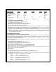
1. RF Programmable Features: Feature Selection 1 Run Time 2 Ign. 2 During Crank 3 Light Output During Run 4 Tach Mode 5 NA 6 Trouble Shooting 7 Door Locks 1 Flash 5 Min. Off Steady NA NA Off 1 Sec/1 Sec 2 Flash 10 Min. On Flash Tach NA On 3.5 Sec/3.5 Sec 3 Flash 15 Min. 4 Flash 20 Min. NA NA 1 Sec/Dbl 1 Sec Default 10 Min. On Steady Tach NA Off 1 Sec/1 Sec To program these selectable features: 1. 2. 3. 4. 5. 6. Start with the programming switch in the OFF position.
Multi Coil Pack Adaptor: (Optional) The multi coil pack adaptor, (P/N 136B1400), is designed for use with vehicles that do not respond to single coil tach programming. Although the tach resolution of this circuit is designed to interface direct with most vehicles, there may be an occasion where the following circuit may be required. To use the adaptor, the Green/Black wires must connect to the negative side of the ignition coil(s). 1.
If the unit fails this test, recheck your enable switch connection to the Ground and the Black/White wire of the Audiovox Remote Start Unit. If you have a plug in enable switch, check that the two pin connector is firmly seated in the mating connector on the control module. DO NOT RELEASE THIS VEHICLE TO THE CONSUMER UNTIL YOU CONFIRM THE OPERATION OF THE MANUAL SHUT DOWN / ENABLE FEATURE.
the equivalent reference wire in the vehicle you are installing the Audiovox Remote Start Unit in. 2. Connect the Cathode, (Striped) end, of a 4000 series diode to this reference wire. 3. Connect the Anode, (Non Striped) end, of the diode to one side of the Remote Start enable switch. 4. Connect the other side of the enable switch to the Black/White enable input wire of the Remote Start unit.
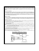
METHOD 1 F. Connect terminal 86 of the relay to a fused +12 volt constant battery source. G. Connect terminal 87 of the relay to the Chime Module side of the previously cut wire in step D. H. Connect terminal 85 of the relay to the Drivers Door side of the pin switch wire previously cut in step B. NOTE: A second 4002 series diode may be required to maintain the integrity of the hood open, shut down circuit. If this is the case, it must be installed as shown in the diagram above.
COMPLETING THE INSTALLATION: After you have confirmed the operation of the Audiovox Remote Start unit and tested all the safety features of the system: 1. If you have not done so already, place the red rubber handle cover over the handle of the control switch for ease of identification. This will allow your customer to distinguish the Remote Start control switch from the program switch. 2. Mount the control module up and behind the dash securing it in place with cable ties or screws.
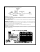
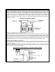
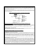
WIRING DIAGRAM © 2000 Audiovox Electronics Corp.