Model APS-55LR Installation Manual 3 Channel Remote Start / Keyless Entry System Installation Instructions This Unit Is Intended For Installation In Vehicles With 12 Volt Negative Ground Electrical Systems, Gasoline or Diesel With True Tach Reference And Automatic Transmissions Only.
The APS-55 Remote Start/Keyless Entry System is designed for use with Automatic Transmission Vehicles Only! The unit provides wait to start input for glow plug pre-heat which will be used for all diesel applications. If this wire is not connected, then the unit will remain in the Gasoline mode setting, which will crank the car when the RF signal is received with no delay.
THE RECEIVER/ANTENNA ASSEMBLY: The Superheterodyne Receiver Antenna Assembly provided with this unit allows routing from below the dashboard for maximum operating range. Choose a location above the belt line (dashboard) of the vehicle for best reception. Special considerations must be made for windshield glass as some newer vehicles utilize a metallic shielded window glass that will inhibit or restrict RF reception. In these vehicles, route the antenna toward a rear window location for best reception.
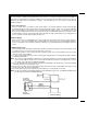
NOTE: This wire must be connected to the vehicle side of the starter cut relay (when used). For the electrical neutral switch configuration, this connection must be made between the starter inhibit relay, (when used) and the neutral safety switch as shown in the following diagram. Failure to connect this wire to the ignition switch side of the neutral safety switch can result in personal injury and property damage. SEE NEUTRAL START SAFETY TEST FOR FURTHER DETAILS.
VIOLET WIRE: Accessory Output Connect this wire to the Accessory wire from the ignition switch. This wire will show + 12 volts when the ignition switch is turned to the "ACCESSORY" or "ON" and "RUN" positions and will show 0 volts when the key is turned to the "OFF" and "START" or "CRANK" positions. WIRING CONNECTIONS: 12 Pin Input / Output Harness Black Wire: Chassis Ground Source Connect the Black wire to a known vehicle ground source or to a solid clean metal part of the chassis.
BROWN w/ BLACK Tracer Wire: Positive Inhibit Input 2 Any time + 12 Volts is applied to the Brown w/ Black tracer wire, the Remote Starter will stop operating, even if the signal is received from the transmitter. If the brake light switch in the vehicle switches + 12 Volts to the brake light circuit, connect the Brown w/ Black trace wire to the output of the brake light switch. If the brake light switch in the vehicle switches ground, do not use the Brown w/ Black wire; see Gray w/ Black tracer wire.
LIGHT BLUE Wire: Ignition 3 / Shock Disable Output This wire provides a 300mA ground output that becomes active 3 seconds before the Remote Start Unit initializes, and remains grounded while running plus an additional 4 seconds after the Remote Start Unit turns off. In all of the applications described below, a relay will be required. The Light Blue wire can be used to accommodate the following situations: A.
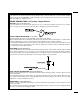
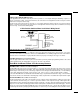
General Motors VATS By-Pass Diagram DARK GREEN Wire: Tach Sensor Input This wire will continually monitor the engine tach rate while the unit is under power of the Remote Start module. This wire will be routed to the vehicle ECM tach input or through the firewall into the engine compartment and connect to the negative side of the ignition coil. This Remote Start unit learns the tach rate of the vehicle and in most cases will operate properly from one multi coil pack regardless of the number of cylinders.
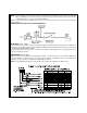
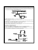
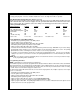
3 Wire Ground Switched Door Lock/Unlock Wiring Detail 3 Wire Positive Switched Door Locks: In this application, the Red wire of the two pin harness provides a + 12 volt pulse during the disarming sequence, or pulsed 12 volt unlock output. Connect the Red wire to the low current 12 volt signal wire from the factory door unlock switch to the factory door unlock relay. The Green wire of the two pin harness provides a + 12 volt pulse during the arming sequence or pulsed 12 volt lock output.
this wire is not used. Be sure to fuse the wire with a 1 Amp Fuse when connecting to a high current circuit such as a factory glow plug wire. The fuse should be installed as close to the high current wire as possible. 3 Pin Antenna/Receiver Connector: (White Connector) Plug the previously routed three pin connector from the antenna receiver assemble into the mating connector of the control module. This connector supplies 12 volts, ground and RF data from the antenna receiver to the remote start module.
3. Diagnostics: 1. Be sure that programmable feature number #6 is set to the "Diagnostics On" mode. 2. First flip the program switch on, then turn the ignition key to the "ON" position. 3. The lights will flash and the number of flashes will indicate the reason for shutdown on the last remote start attempt. The indications are as follows. 1 Flash 5, 10, 15, or 20, minute run timer expired. 2 Flashes Low or No tach signal received. 3 Flashes Positive or Negative input shut down.
WA R N I N G ! ! DO NOT RELEASE THIS VEHICLE TO THE CONSUMER UNTIL YOU CONFIRM THE OPERATION OF THE HOOD PIN SAFETY SHUT DOWN FEATURE. MANUAL SHUT DOWN / ENABLE CIRCUIT: The intent of the manual shut down / enable circuit is to allow the vehicle operator to prevent operation of the Remote Start Unit regardless of the RF transmitter operation. To test the integrity of the manual shut down / enable circuit: 1. Place the control switch in the on (Closed To Ground) position. 2.
from the ignition cylinder. This configuration prevents mechanical operation while the vehicle is in gear but offers no consideration for electrical operation. Because of this potential problem, this installation requires the additional connection of a safety wire from the remote start device to the vehicle Park/Neutral ECM Input or the vehicle key in sensor. This connection will prevent remote start operation if the key is left in the ignition switch regardless of the gear selector position.
Method 2 will allow the safety required for the remote start unit and prevent the vehicle from starting while in any gear other than Park or Neutral while the key is in the ignition cylinder. However, the original factory key in chime module will not alert the owner that the key has been left in the ignition switch. In addition, this may also effect other warning tones such as the light on reminder.
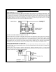
NOTE: A second 4002 series diode may be required to maintain the integrity of the hood open, shut down circuit. If this is the case, it must be installed as shown in the diagram above. The anode (Non Striped) side must be connected to the Gray/Black wire of the Remote Start Unit. The cathode (Striped) side must be connected to the hood pin switch.
© 2001 Audiovox Electronics Corp.