Model APS-56 Installation Manual 3 Channel Remote Start / Keyless Entry System Installation Instructions This Unit Is Intended For Installation In Vehicles With 12 Volt Negative Ground Electrical Systems, Gasoline or Diesel With True Tach Reference And Automatic Transmissions Only.
This Remote Start/Keyless Entry System is designed for use with Automatic Transmission Vehicles Only! The unit provides wait to start input for glow plug pre-heat which will be used for all diesel applications. If this wire is not connected, then the unit will remain in the Gasoline mode setting, which will crank the car when the RF signal is received with no delay.
THE RECEIVER/ANTENNA ASSEMBLY: The Superheterodyne Receiver Antenna Assembly provided with this unit allows routing from below the dashboard for maximum operating range. Choose a location above the belt line (dashboard) of the vehicle for best reception. Special considerations must be made for windshield glass as some newer vehicles utilize a metallic shielded window glass that will inhibit or restrict RF reception. In these vehicles, route the antenna toward a rear window location for best reception.
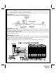
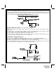
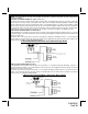
NOTE: This wire must be connected to the vehicle side of the starter cut relay (when used). For the electrical neutral switch configuration, this connection must be made between the starter inhibit relay, (when used) and the neutral safety switch as shown in the following diagram. Failure to connect this wire to the ignition switch side of the neutral safety switch can result in personal injury and property damage. SEE NEUTRAL START SAFETY TEST FOR FURTHER DETAILS.
VIOLET WIRE: Accessory Output Connect this wire to the Accessory wire from the ignition switch. This wire will show + 12 volts when the ignition switch is turned to the "ACCESSORY" or "ON" and "RUN" positions and will show 0 volts when the key is turned to the "OFF" and "START" or "CRANK" positions. WIRING CONNECTIONS: 12 Pin Input / Output Harness Black Wire: Chassis Ground Source Connect the Black wire to a known vehicle ground source or to a solid clean metal part of the chassis.
BROWN w/ BLACK Tracer Wire: Positive Inhibit Input 2 Any time + 12 Volts is applied to the Brown w/ Black tracer wire, the Remote Starter will stop operating, even if the signal is received from the transmitter. If the brake light switch in the vehicle switches + 12 Volts to the brake light circuit, connect the Brown w/ Black trace wire to the output of the brake light switch. If the brake light switch in the vehicle switches ground, do not use the Brown w/ Black wire; see Gray w/ Black tracer wire.
LIGHT BLUE Wire: Ignition 3 / Shock Disable Output This wire provides a 300mA ground output that becomes active 3 seconds before the Remote Start Unit initializes, and remains grounded while running plus an additional 4 seconds after the Remote Start Unit turns off. In all of the applications described below, a relay will be required. The Light Blue wire can be used to accommodate the following situations: A.
Green/Orange Wire: Tach Sensor Input This wire will continually monitor the engine tach rate while the unit is under power of the Remote Start module. This wire will be routed to the vehicle ECM tach input or through the firewall into the engine compartment and connect to the negative side of the ignition coil. This Remote Start unit learns the tach rate of the vehicle and in most cases will operate properly from one multi coil pack regardless of the number of cylinders.
NOTE: The outputs above are low current outputs and must be used with a relay if the circuit's requirement is more than 300 mA. 2 Pin Door Lock/Unlock Harness: (White Connector) The Red & Green Door Lock/Unlock output wires provide either a pulsed ground or pulsed + 12 volts to control the vehicle door lock / unlock circuits. The output of these wires has a maximum switching capability of 300mA.
Resistive Circuits, As Well As 4 Wire Polarity Reversal and 5 Wire Alternating 12 Volt Door Lock Control Circuits These applications require the use of additional components which may include relays, fixed resistors, or for convenience, the AS 9159 Door Lock Interface. Refer to the AUDIOVOX Door Lock Wiring Supplement and or the Audiovox fax back service for information on your particular vehicle for properly connecting to these types of circuits.
first programming tach, the unit will flash the parking lights 7 times indicating tach has not been learned and stored. If the tach rate is not properly programmed to the specific vehicle, the unit may not realize that the vehicle is running in certain instances and could re-engage the starter motor. The Remote Car Starter will learn the tach rate of most vehicles single ignition coils, multiple coil packs, and or single injector. To learn tach; 1. Turn the ignition key to the ON position. 2.
Device. It is the responsibility of the installing technician to complete these tests. Failure to test the unit in the following manner may result in personal injury, property damage, or both. HOOD PIN SAFETY SHUT DOWN: The intention of the hood pin safety shut down is to prevent the Remote Start unit from being activated while a mechanic or vehicle owner is performing normal routine vehicle maintenance. To test the integrity of this circuit: 1.
Neutral Safety Switch provided below will help you to determine if the vehicle you are working on has this type of safety switch and will provide alternate wiring methods to accommodate this situation. WA R N I N G ! ! REMEMBER TO RECONNECT THE BROWN/BLACK WIRE TEMPORARILY DISCONNECTED IN STEP 3. DO NOT RELEASE THIS VEHICLE TO THE CONSUMER UNTIL YOU CONFIRM THE OPERATION OF THE NEUTRAL SAFETY START FEATURE.
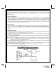
considering either alternative. Method 1 will allow the safety required for the remote start unit and prevent the vehicle from starting while in any gear other than Park or Neutral while the key is in the ignition cylinder. However, if the key is left in the ignition switch and the door is left opened, the added relay will be energized causing a 150mA drain on the battery.
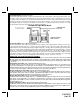
METHOD 2 To connect to the key in sensor circuit as shown for method 2: A. Locate the control wire that connects the drivers door pin switch to the key in sensor switch. B. Cut this wire and connect the ignition cylinder side to chassis ground. C. Locate the key in sensor switch wire that connects the chime module to the ignition cylinder . D. Cut this wire and connect the ignition cylinder side to the Remote Start Negative Safety Shut down Wire Gray/Black, using a 4002 series diode as shown above.
© 2005 Audiovox Electronics Corp.