APS-700 Installation Guide Remote Control Security System With Pager/Satellite Control Interface Installation Instructions Kit Contents APS-700 Control Module 4 Channel Code Learning Receiver 2 Three Button Anti-Code Grabbing Transmitters Six Tone Multi-Tone Siren Starter Inhibit Relay w/Socket Main Wiring Harness Auxiliary Wiring Harness Plug In Valet Plug In 2/Pin Door Lock Harness Plug In LED 2 Pin Accessory VSS Harness 4 Pin Shock Sensor Harness Plug In Two Stage Shock Sensor Pin Switch Hardware Bag I
The APS-700 is a full featured security system with on board paging technology that provides the consumer a direct link to their vehicle from anywhere in the world. This patent pending technology allows the user to operate the vehicle from any land or mobile telephone.
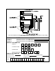
VALET/PROGRAM SWITCH: Select a mounting location that is easily accessible to the operator of the vehicle. The switch can be mounted to the lower dash panel in the driver's area. Inspect behind the chosen location to insure that adequate clearance is allowed for the body of the switch, as well that the drill will not penetrate any existing factory wiring or fluid lines. Drill a 1/4" hole in the desired location and mount the switch by passing it through the panel from the underside.
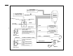
White w/ Black Trace Wire: Positive (+) Siren Output This is the positive siren feed wire. Route this wire through a grommet in the firewall to the siren location. Connect the White w/ Black Trace wire to the Red wire of the Siren. Secure the Black wire of the Siren to a known chassis ground or solid clean metal surface. Black Wire: Chassis Ground Source Connect the Black wire to a known vehicle ground source or to a solid clean metal part of the chassis.
Dark Green Wire: (-) Instant Trigger Zone 2 The Dark Green wire is the instant on ground trigger input wire. This wire must be connected to the hood and trunk pin switches previously installed. Note: This wire will be shunted when remote control channel 2 is accessed, (trunk release). This wire will remain shunted all the while there is ground present, and for 5 seconds after the ground is removed.
2 Pin Auxiliary Harness: (Red Connector) The two pin auxiliary connector is used to control vehicle shut down from a paging theft command. See supplement for wiring information. Connecting The Dash Mounted LED: Plug the two pin white connector from the previously installed LED into the mating two pin white female connector shell of the control module. Connecting The APS-700 Module: Re-connect the vehicle's battery then plug the main and mini connectors into the mating connector shells of the control module.
Connecting And Adjusting The Shock Sensor: Route the 4 pin cable from the previously installed shock sensor to the control module. Plug it into the mating 4 pin white connector shell located along side the 8 pin main harness connector of the control unit. Pre- adjust the previously installed Shock Sensor by first accessing the potentiometer setting screw and carefully turn this adjustment all the way counterclockwise. Now Turn the adjuster clockwise to the first notch on the module case.
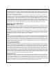
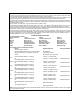
LEFT FRONT & REAR COMMON RIGHT FRONT & REAR COMMON RIGHT SIDE 8
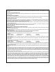
THE FOLLOWING OPTIONS HAVE BEEN INSTALLED AND ARE CONNECTED TO THE ALARM AND PAGER OUTPUTS AS SHOWN ALARM PAGER CHANNEL 2 CHANNEL 3 CHANNEL 4 AUXILIARY OUTPUT 1 IS CONNECTED TO AUXILIARY OUTPUT 2 IS CONNECTED TO AUXILIARY OUTPUT 3 IS CONNECTED TO PRODUCT INFORMATION SERIAL # COUNTRY CODE DLR/DIST ID# INSTALLATION DATE VEHICLE INFORMATION VEHICLE YEAR VEHICLE MFG. VEHICLE COLOR LICENSE PLATE# VIN# 9 VEHICLE MOD.
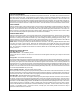
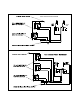
SHOCK SENSOR RED, BLACK, BLUE AND GREEN WIRES TO PLUG IN SHOCK SENSOR +12 VOLT BATTERY CONNECT TO A +12 VOLTS FULL TIME BATTERY SOURCE RED w/WHITE MODULE APS-700 Cut Existing Low Current To +12 Volt IGN.
APS - 700 DOOR LOCK OUTPUTS (+) LOCK PULSE (-) UNLOCK PULSE CAUTION: Data Connection For Upgrade Vehicle Tracking Module Only GREEN (+) UNLOCK PULSE (-) LOCK PULSE RED LED RED VSS IGNITION CONTROL SEE SPECIAL NOTE CONCERNING THIS APPLICATION VALET/PROGRAM SWITCH BLACK BLUE RED BLACK GRAY ZONE 1 Connect to Optional Negative Triggering Devices CHANNEL 4 /AUXILIARY 3 Negative Latching Output For Optional Window Roll-Up or Remote Start CHANNEL 3/AUXILIARY 2 Negative Latching Output For Optional Acc
VSS WIRING SUPPLEMENT The two pin auxiliary harness with the red connector shell provides a input signal to the control module from the vehicle's Speed Sensor ( VSS), and provides a low current ground switched output to control a shut down relay. The relay can be used to interrupt any circuit in the vehicle which will cause the vehicle's engine to stop running.
Modelo APS-700 Guía de instalación Sistema de seguridad a control remoto con sistema de aviso/interfaz de control de satélite Instrucciones de instalación Contenido del kit: Módulo de control APS-700 Receptor con captación de código de 4 canales 2 transmisores de 3 botones con escalonamiento de frecuencias de código Sirena de seis tonos Relé para bloquear el arranque con casquillo adaptador Arnés de cableado principal Arnés de cableado auxiliar Connecte el Valet Arnés de trabado de puertas con dos clavijas
El sistema APS 700 es un sistema de seguridad de múltiples funciones con la tecnología de aviso incorporada que proporciona al consumidor en enlace directo con su vehículo desde cualquier lugar del mundo. Esta nueva tecnología, cuya patente se encuentra pendiente, permite al usuario operar el vehículo desde cualquier teléfono común o móvil.
INTERRUPTOR VALET / PROGRAMACIÓN : Elija un lugar de montaje al que el operador del vehículo tenga fácil acceso. Se puede montar el interruptor en el panel inferior del tablero en el área del conductor. Asegúrese de fijarse detrás del tablero para comprobar si hay el suficiente espacio para la caja del interruptor y para confirmar que el taladro no vaya a dañar ninguno de los componentes existentes cuando pase a través del tablero de instrumentos.
Cable testigo blanco y negro: Salida positiva de la sirena (+) Es una cable de alimentación positiva de la sirena. Pase este cable por un ojal del muro contrafuego hacia el lugar de la sirena. Conecte el cable testigo blanco y negro de la sirena. Fije el cable negro de la sirena a una conexión a tierra del chasis o a una superficie metálica limpia y sólida.
Cable verde oscuro: Entrada (-) de activación instantánea Zona 2 Es el cable de entrada de activación instantánea o conexión a tierra. Este cable tiene que estar conectado a los interruptores de clavija del capó o baúl que se instalaron antes. Nota: Este cable se derivará cuando se acceda al canal 2 del control remoto (desenganche del baúl). Este cable quedará derivado mientras hay una conexión a tierra y durante 5 segundos después de que se quite la conexión a tierra.
Arnés auxiliar de 2 clavijas (conector rojo): Se usa el conector auxiliar de 2 clavijas para controlar el apagado del vehículo con un comando de robo enviado por el sistema de aviso. Ver suplemento para obtener información de cableado. Conexión del indicador LED que va montado en el tablero: Enchufe el conector blanco de dos clavijas del indicador LED ya instalado en conector hembra blanco de dos clavijas del módulo de control.
Conexión y ajuste del detector de choque: Pase el cable de 4 clavijas del detector de choque ya instalado hacia el módulo de control. Enchúfelo en el conector blanco de 4 clavijas ubicado al lado del conector de 8 clavijas del conector del arnés de la unidad de control. Ajuste el detector de choque ya instalado accediendo primero al tornillo de ajuste del potenciómetro y girando cuidadosamente este ajuste completamente en dirección contraria a las agujas del reloj.
DELANTERA Y TRASERA IZQUIERDAS EN COMÚN DELANTERA Y TRASERA DERECHAS EN COMÚN A LA FUENTE DE +12 VOLTIOS CON FUSIBLES LADO IZQUIERDO AL PRIMER CABLE BLANCO DEL MÓDULO DE CONTROL LADO DERECHO AL SEGUNDO CABLE BLANCO DEL MÓDULO DE CONTROL Corte DEL INTERRUPTOR DIRECCIONAL DEL VEHÍCULO A LA FUENTE DE +12 VOLTIOS CON FUSIBLES TRASERAS EN COMÚN Y DELANTERAS INDEPENDIENTES LADO IZQUIERDO LADO DERECHO AL PRIMER CABLE BLANCO DEL MÓDULO DE CONTROL BOMBILLAS TRASERAS AL SEGUNDO CABLE BLANCO DEL MÓDULO DE
TODAS LAS 4 BOMBILLAS INDEPENDIENTES A LA FUENTE DE +12 VOLTIOS CON FUSIBLES delantera izquierda delantera derecha AL PRIMER CABLE BLANCO DEL MÓDULO DE CONTROL trasera izquierda trasera derecha AL SEGUNDO CABLE BLANCO DEL MÓDULO DE CONTROL Corte DEL INTERRUPTOR DIRECCIONAL DEL VEHÍCULO SE HAN INSTALADO Y CONECTADO LAS SIGUIENTES OPCIONES A LAS SALIDAS DE LA ALARMA Y EL SISTEMA DE AVISO SEGÚN SE ILUSTRA ALARMA CANAL 2 CANAL 3 CANAL 4 SISTEMA DE AVISO SALIDA AUXILIAR 1 ESTÁ CONECTADA A __________ SAL
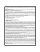
DETECTOR DE CHOQUE CABLES ROJO, NEGRO, AZUL Y VERDE PARA ENCHUFAR EL DETECTOR DE CHOQUE BATERÍA DE +12 VOLTIOS CONECTAR A UNA BATERÍA DE +12 VOLTIOS CONSTANTES ROJO Y BLANCO Corte Baja corriente existente Al ENCENDIDO / ARRANQUE +12 voltios Rojo MÓDULO APS-700 Cable solenoide de arranque NARANJA BLANCO SALIDA DE BAJA CORRIENTE DESTELLADO DE LUCES DEL LADO IZQUIERDO VER NOTAS ESPECIALES CON RESPECTO A LA APLICACIÓN BLANCO SALIDA DE BAJA CORRIENTE DESTELLADO DE LUCES DEL LADO DERECHO VER NOTAS ESPE
APS - 700 SALIDAS DE TRABADO DE PUERTAS IMPULSO (+) DE TRABADO IMPULSO (-) DE DESTRABADO IMPULSO (+) DE DESTRABADO IMPULSO (-) DE TRABADO PRECAUCIÓN: Conexión de datos para actualizar el módulo de rastreo del vehículo solamente.
SUPLEMENTO DE CABLEADO DEL VSS El arnés de cableado auxiliar de dos clavijas que tiene el conector rojo proporciona una señal de entrada al módulo de control del Detector de velocidad del vehículo (VSS por las siglas en inglés) y proporciona una salida conmutada de conexión a tierra de baja corriente para controlar un relé de apagado. Se puede usar el relé para interrumpir cualquier circuito del vehículo que haga parar al motor del vehículo.