Model APS 786 Installation Manual 4 Channel Remote Car Starter With Full Feature Alarm System Installation Instructions This Unit Is Intended For Installation In Vehicles With 12 Volt Negative Ground Electrical Systems, Gasoline or Diesel With True Tach Reference And Automatic Transmissions Only.
The APS-785 Remote Start/Alarm System is designed to be used with Automatic Transmission Vehicles Only! The unit provides a selectable ignition control that allows a number of selectable timed outputs for glow plug pre-heat which may be required for certain diesel vehicles, (see selectable feature #9). If the diesel engine has a instant fire, (no glow plug pre-heat system), feature #9 should remain in the default Gasoline mode setting.
THE RECEIVER/ANTENNA ASSEMBLY: The Superheterodyne Receiver Antenna Assembly provided with this unit allows routing from below the dash board for maximum operating range. Choose a location above the belt line (dashboard) of the vehicle for best reception. Special considerations must be made for windshield glass as some newer vehicles utilize a metallic shielded window glass that will inhibit or restrict RF reception. In these vehicles, route the antenna toward a rear window location for best reception.
WIRING THE 6 PIN MAIN POWER HARNESS: RED w/ WHITE Trace Wire: + 12 volts Battery 1 Source Connect this wire to a + 12 VDC constant source found at the vehicle's ignition switch using the 30 Amp fuse and holder provided. This wire provides power for the control circuit as well as the ignition 1 and ignition 2 relays.
YELLOW START WIRE DETAIL GREEN Wire: Ignition 2 Output Connect this wire to the ignition 2 wire from the ignition switch. This wire will show + 12 volts when the ignition key is turned to the "ON" or "RUN" position and is some cases the "START" or CRANK" position. This wire will show 0 volts when the key is turned to the "OFF" and "ACCESSORY" positions. NOTE: See programming information concerning this wire to allow output during the "START" mode.
WIRING CONNECTIONS: Multi Pin Accessory Input/Output Harness White w/ Red Trace Wire: Parking Light Flasher Feed This wire is the common contact of the on board parking light flasher relay. If the vehicle you are working on has +12 volt switched parking lights, connect this wire to a fused + 12 volt source. (Max. 15 Amps) NOTE: If the vehicle's parking lights are ground switched, connect this wire to chassis ground.
Purple Wire: (+) Door Trigger Input If the vehicle's door courtesy light switches + 12 volts when the door is opened, (Some Fords and some Imports), you must connect this wire to the positive output from one of the vehicle's door pin switches. In most cases, the Purple wire will need to be connected to only one door switch no matter how many doors the vehicle has as most door lighting circuits are wired in parallel.
Light Blue Wire: Ignition 3 Output This wire provides a 300mA ground output that becomes active 3 seconds before the Remote Start Unit initializes, and remains grounded while running plus an additional 4 seconds after the Remote Start Unit turns off. In all of the applications described below, a relay will be required. The Light Blue wire can be used to accommodate the following situations: A.
Green w/ White trace Wire: Entry Illumination Ground Output This wire provides a 30 second ground output (300 mA Max.) whenever the remote is used to disarm the alarm or to unlock the doors and provides a continuous pulsed output whenever the alarm is triggered. This wire should be connected to an external relay, and wired to the vehicles interior entry lighting whenever the optional Interior Illumination circuit is desired. See below for relay wiring details.
Orange Wire: Ground When Armed Output This wire provides a 300 mA ground output when the alarm circuit is armed to control the starter inhibit relay. Connect the Orange wire to terminal #86 (orange wire) of the relay provided. Connect terminal #85 (red wire) of the relay to an ignition wire in the vehicle that is +12 volts when the ignition switch is turned to the on and start positions and off when the key is off.
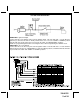
Black Wire: Chassis Ground Source Connect the Black wire to a known vehicle ground source or to a solid clean metal part of the chassis. Be certain to remove any paint or grease and secure this wire with a self taping screw and ring terminal. Chassis Ground Connection Detail Green w/ Orange Trace Wire: Tachometer Input Signal This wire will continually monitor the engine's tach rate while the unit is under power of the Remote Start module.
Dark Blue Wire: Delayed 300mA Pulsed Channel 3 Output The Dark Blue wire supplies a 300mA ground pulsed output whenever channel three of the receiver is accessed. Pressing the pre-programmed transmitter button for three seconds will access channel two. This is a low current output and must be connected to a relay to supply power to the trunk release or the circuit you wish to control. Connect the Dark Blue wire to terminal # 86 of a VF45F11 P&B relay or equivalent.
started under control of the remote start unit. Typically this wire will be used to re-lock the vehicle doors if the doors unlock automatically when the factory anti-theft system is disarmed. Black w/ Red Trace Wire: Pulsed Ground Output After Shutdown The Black w/ Red Trace wire will provide a 1 second 300 mA pulsed ground output after the remote start unit shuts down. This output will occur regardless of whether the circuit times out or is manually terminated.
3 Wire Ground Switched Door Lock Circuits: In this application, the Red wire of the door lock harness provides a ground pulse during the arming sequence, or pulsed ground lock output. Connect the Red wire to the low current ground signal wire from the factory door lock switch to the factory door lock relay. The Green wire of the door lock harness provides a ground pulse during the disarming sequence, or pulsed ground unlock output.
lock/unlock motor legs rest at + 12 volts and switches ground to the door lock/unlock motors, connect the remaining terminal, 87, to chassis ground. The Red/Black wire provides a pulse ground output when the unlock button of the transmitter is pressed a second time after disarming. Connect the Red/Black wire to the wire that provides a low current ground signal from the factory door unlock switch to the factory door unlock control relay.
Note: Resistive Circuits, As Well As 4 Wire Polarity Reversal and 5 Wire Alternating 12 Volt Door Lock Control Circuits These applications require the use of additional components which may include relays, fixed resistors, or for convenience, the AS 9159 Door Lock Interface. Refer to the AUDIOVOX Door Lock Wiring Supplement and or the Audiovox fax back service for information on your particular vehicle for properly connecting to these types of circuits.
To program these selectable features; First Second Third Fourth Fifth Sixth Seventh Eighth Ninth Tenth Action Turn ignition on Press and release the valet switch 3 times Within 3 seconds, turn ignition Off System Response No response 1 Chirp - LED 1 flash Short chirp, then long chirp Then On Press transmitter Lock button to change Press transmitter Lock button to change or Press and release the valet switch Press transmitter Lock button to change or Press and release the valet switch Press tran
TIMED START PROGRAM: The Remote Start unit has the ability to start the vehicle automatically at timed intervals. This feature is useful in extremely cold climates where starting the engine is the only means to keep the battery charged and fluids warm. The operator has the option to have the unit start every 2 or 4 hours for a maximum of 48 hours. Factory pre-set is to start at 4 hour intervals. To select 2 or 4 hour automatic start timer: 1. Start with the Enable switch (Red Handle) in the "On" Position.
NOTE: Once you've entered the program mode DO NOT allow more than 15 seconds to pass between steps, or the programming mode will be terminated. Programming Tach Rate: NOTE: All applications require that tach be programmed. The unit will not operate unless tach is programmed. If an attempt is made to start the vehicle via the remote start without first programming tach, the unit will flash the parking lights 7 times indicating tach has not been learned and stored.
4. Connect the Green wire to the (Green) or (Orange/Green) tach input of the Audiovox remote start unit. TESTING YOUR INSTALLATION: CAUTION!! The following procedure must be performed after the installation of an Audiovox Remote Start Device. It is the responsibility of the installing technician to complete these tests. Failure to test the unit in the following manner may result in personal injury, property damage, or both.
To test the integrity of the Neutral Start Safety Circuit: 1. Set the vehicle parking brake. 2. Block the drive wheels to prevent vehicle movement. 3. Temporarily disconnect the Brown/Black positive shut down wire from the vehicle's brake switch. 4. Sitting in the vehicle, start the engine using the vehicle's ignition key. 5. Step on the brake pedal and shift the gear selector into reverse. 6. Allow the transmission to shift.
DO NOT RELEASE THIS VEHICLE TO THE CONSUMER UNTIL YOU CONFIRM THE OPERATION OF THE NEUTRAL SAFETY START FEATURE. KEY IN SENSOR CIRCUITS: If the vehicle you are working on does not have or you cannot locate the ECM reference wire, there are two alternatives available. Although not preferred, the vehicle Key In Sensor may be reconfigured to allow a margin of safety and will prevent the vehicle with a Mechanical Neutral Start Switch from starting in gear.
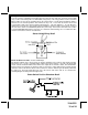
METHOD 2 To connect to the key in sensor circuit as shown for method 2: A. Locate the control wire that connects the drivers door pin switch to the key in sensor switch. B. Cut this wire and connect the ignition cylinder side to chassis ground. C. Locate the key in sensor switch wire that connects the chime module to the ignition cylinder . D. Cut this wire and connect the ignition cylinder side to the Remote Start Negative Safety Shut down Wire Gray/Black, using a 4002 series diode as shown above.
© 2003 Audiovox Electronics Corp., Hauppauge, N.Y.