
Installation Manual


128-9312
3 of 24
3
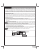
14 Pin Main Wiring Harness #1124305
1 Green/Orange Tachometer input
2 Green/Yellow Glow Plug Input
3 DK. Blue Channel 3 Trunk Release Output (-)
4 Brown/Black (+) Inhibit /Shutdown To Brake Switch
5 Brown (+) Inhibit / Shutdown To Brake Switch
6 Gray (-) Inhibit Neutral Start Switch
7 NA
8 Black/Yellow Pulse During Crank Output (-)
9 Black/Red Pulse After Shut Down Output (-)
10 Black/Blue Pulse Before Start Output (-)
11 Black/LT. Green Pulse After Start Output (-)
12 LT. Blue Ground While Running Output (-)
13 Gray/Black (-) Inhibit / Shutdown To Hood Switch
14 Black/White Horn Output (-)