
Installation Manual

128-9312
6 of 24
6
IMPORTANT!
DO NOT PLUG THE SIX PIN MAIN POWER HARNESS OR THE MULTI PIN INPUT / OUTPUT HARNESS
INTO THE CONTROL MODULE UNTIL ALL CONNECTIONS TO THE VEHICLE HAVE BEEN MADE. AFTER
SELECTING YOUR TARGET WIRES AS DEFINED BELOW, DISCONNECT THE NEGATIVE BATTERY
CABLE FROM THE VEHICLE BATTERY PRIOR TO MAKING ANY CONNECTIONS.
NOTE: Do not remove the fuse holders from this wire harness. Fuses must be used and located as
close as possible to the power source for adequate protection of the vehicle.
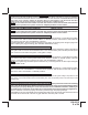
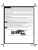
WIRING THE 6 PIN MAIN POWER HARNESS: PART # 1123742
NOTE: Do not remove the fuse holders from this wire harness. Fuses must be used and located as
close as possible to the power source for adequate protection of the vehicle.
1 Blue Wire: Ignition 1 Output
Connect this wire to the ignition 1 wire from the ignition switch. This wire will show +12 Volts when the ignition
key is turned to the "ON" or "RUN" and the "START" or CRANK" positions, and will have 0 Volts when the
key is turned to the "OFF" and "ACCESSORY" positions.
For Diesel Applications, this wire must be connected to the ignition circuit that powers the glow plugs if the
vehicle requires glow plug pre-heating. (See selectable feature Bank 3 #12)
2 Red/White Wire: +12 Volt Battery 1 Source Fused 30A
Locate the vehicle battery wire(s) at the ignition switch. Verication: This wire will register voltage in all positions
of the ignition switch. Connect the Red w/White Wire to the vehicle's battery wire. This wire provides power
for the control circuit as well as the ignition 1 and ignition 2 relays.
3 Green Wire: Ignition 2 Output
Connect this wire to the ignition 2 wire from the ignition switch. This wire will show +12 Volts when the ignition
key is turned to the "ON" or "RUN" position and is some cases the "START" or CRANK" position. This wire
will show 0 Volts when the key is turned to the "OFF" and "ACCESSORY" positions.
NOTE: See programming information (Bank 3 Selection #7) concerning this wire to allow output during the
"START" mode.
4 Purple Wire: Accessory Output
Connect this wire to the Accessory wire from the ignition switch. This wire will show +12 Volts when the ignition
switch is turned to the "ACCESSORY" or "ON" and "RUN" positions, and will show 0 Volts when the key is
turned to the "OFF" and "START" or "CRANK" positions.
5 Red Wire: +12 Volt Battery 2 Source Fused 30A
Locate the vehicle battery wire(s) at the ignition switch. Verication: This wire will register voltage in all positions of the
ignition switch. Connect the Red Wire to the vehicle's battery wire. This wire provides power for the start relay and the
accessory relay.
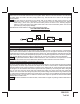
6 Yellow Wire: Starter Output
Careful consideration for the connection of this wire must be made to prevent the vehicle from starting
while in gear. Understanding the difference between a mechanical and an electrical Neutral Start Switch
will allow you to properly identify the circuit and select the correct installation method. In addition you
will realize why the connection of the safety wire is required for all mechanical switch congurations.
Failure to make this connection properly can result in personal injury and property damage.
In all installations it is the responsibility of the installing technician to test the remote start unit and ensure that
the vehicle cannot start via RF control in any gear selection other than park or neutral.