Model APS 675 Installation Manual 3 Channel Remote Start / Keyless Entry System Installation Instructions This Unit Is Intended For Installation In Vehicles With 12 Volt Negative Ground Electrical Systems, Gasoline or Diesel With True Tach Reference And Automatic Transmissions Only.
The APS-675 Remote Start/Keyless Entry System is designed to be used with Automatic Transmission Vehicles Only! The unit provides a selectable ignition control that allows a 10 second output for glow plug pre-heat which may be required for certain diesel vehicles, (see selectable feature #9). If the diesel engine has a instant fire, (no glow plug pre-heat system), feature #9 should remain in the default Gasoline mode setting.
allowed for the body of the switch, and also that the drill will not penetrate any existing factory wiring or fluid lines. Drill a 1/4" hole in the desired location and mount the switch by passing it through the panel from the underside. Secure the switch using the nut, star washer, and on/off face plate. It is suggested that the switch be oriented to allow the on position to be up toward the driver and the off position to be down or away from the driver. Route the switch wires toward the control module.
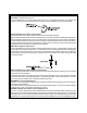
used ) and the neutral safety switch as shown in the following diagram. Failure to connect this wire to the ignition switch side of the of the neutral safety switch can result in personal injury and property damage. SEE NEUTRAL START SAFETY TEST FOR FURTHER DETAILS. BLUE Wire: Ignition 1 Output Connect this wire to the ignition 1 wire from the ignition switch.
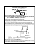
WIRING CONNECTIONS: 12 Pin Input / Output Harness Black Wire: Chassis Ground Source Connect the Black wire to a known vehicle ground source or to a solid clean metal part of the chassis. Be certain to remove any paint or grease and secure this wire with a self taping screw and ring terminal. BLACK w/WHITE Tracer Wire: Control Switch The Black w/ White tracer wire provides ON-OFF control of the Remote Starter.
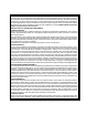
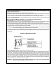
Brake Switch Positive Shutdown Detail YELLOW w/ BLACK Tracer Wire: + 12 Volt Alarm By - Pass Output NOTE: YOU MUST DISCONNECT THE IGNITION INPUT OF THE ALARM FROM ANY OTHER WIRE THAT IT IS PRESENTLY CONNECTED TO IN THE VEHICLE. This wire provides a + 12 Volt output when the ignition key is turned to the “ON” position, and 0 Volts when the ignition key is “OFF” and when the vehicle is running under the control of the remote starter. This wire should be connected to the ignition input of the alarm system.
The Light Blue wire can be used to accommodate the following situations: A. Shock Sensor By Pass: If there is Shock Sensor used with an alarm system and it is not shunted during the Remote Start activation period, then vibration from the running vehicle can cause the alarm to trigger. In this case, connect the Light Blue Wire to terminal #86 of a external relay. Connect terminal# 85 of the relay to a fused + 12 volt battery source.
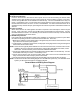
DARK GREEN/ORANGE Wire: Tach Sensor Input This wire will continually monitor the engine tach rate while the unit is under power of the Remote Start module. This wire will be routed to the vehicle ECM tach input or through the firewall into the engine compartment and connect to the negative side of the ignition coil. This Remote Start unit learns the tach rate of the vehicle and in most cases will operate properly from one multi coil pack regardless of the number of cylinders.
3 Wire Positive Switched Door Locks: In this application, the Red wire of the two pin harness provides a + 12 volt pulse during the disarming sequence, or pulsed 12 volt unlock output. Connect the Red wire to the low current 12 volt signal wire from the factory door unlock switch to the factory door unlock relay. The Green wire of the two pin harness provides a + 12 volt pulse during the arming sequence, or pulsed 12 volt lock output.
Typically this output will be used to re-lock the vehicle doors if the doors unlock automatically when the ignition circuit transitions to off. Black w/ Yellow Trace Wire: Ground Output During Start (Crank) The Black w/ Yellow Trace wire will provide a 300 mA ground output while the starter output of the remote start unit is active. This output can be used to activate the Crank Low/Bulb Test wire found in some GM vehicles. This wire is also referred to as the ECM wake up wire in some Chrysler vehicles.
Dark Blue/Black and Green/White - 2 Pin Input/Output Harness: Dark Blue/Black Trace Wire: External Trigger Input The Dark Blue/Black trace wire allows the remote start unit to be activated from an external source. The intent of this wire is to allow the unit to be controlled from a "POSSE/CAR-LINK" paging system or similar device. When this wire receives a ground pulse, the unit will start the vehicle. Connect this wire to a ground pulsed output from the controlling circuit.
To program these selectable features: 1. Start with the programming switch in the OFF position. 2. Turn the ignition key to the ON position. 3. Flip the program switch ON - OFF - ON - OFF - ON - then OFF. 4. Immediately turn the ignition key OFF, then back to ON. 5. Flip the program switch ON - OFF - ON - then OFF. 6. Usebutton1onthetransmittertoadvancetothefeaturethatyouwanttochange.
TIMED START PROGRAM: The Remote Start unit has the ability to start the vehicle automatically at timed intervals. This feature is useful in extremely cold climates where starting the engine is the only means to keep the battery charged and fluids warm. The operator has the option to have the unit start every 2 or 4 hours for a maximum of 48 hours. Factory pre-set is to start at 4 hour intervals. To select 2 or 4 hour automatic start timer: 1. Start with the Enable switch (Red Handle) in the "On" Position.
To test the integrity of this circuit: 1. With the driver's window in the down position, start the vehicle using the RF transmitter. 2. Reach inside the car and pull the hood release. 3. Raise the hood and confirm that the remote start unit shuts down. If the unit fails this test, recheck your pin switch connection to the Gray/Black wire of the Audiovox Remote Start Unit. DO NOT RELEASE THIS VEHICLE TO THE CONSUMER UNTIL YOU CONFIRM THE OPERATION OF THE HOOD PIN SAFETY SHUT DOWN FEATURE.
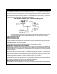
MECHANICAL NEUTRAL SAFETY SWITCH CONSIDERATIONS: Mechanical neutral safety switch configurations differ slightly in that they do not offer the same level of safety when installing a remote start device. Often when the ignition switch is turned off while the gear selector is in any position other than park or neutral, the mechanical function will not allow the key to be turned to the start position or be removed from the ignition cylinder.
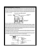
Additional information concerning Key In Sensor methods 1 & 2 are listed below and should be reviewed before considering either alternative. Method 1 will allow the safety required for the remote start unit and prevent the vehicle from starting while in any gear other than Park or Neutral while the key is in the ignition cylinder however, if the key is left in the ignition switch and the door is left opened, the added relay will be energized causing a 150mA drain on the battery.
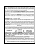
METHOD 2 To connect to the key in sensor circuit as shown for method 2: A. Locate the control wire that connects the drivers door pin switch to the key in sensor switch. B. Cut this wire and connect the ignition cylinder side to chassis ground. C. Locate the key in sensor switch wire that connects the chime module to the ignition cylinder . D. Cut this wire and connect the ignition cylinder side to the Remote Start Negative Safety Shut down Wire Gray/Black, using a 4002 series diode as shown above.
WIRING DIAGRAM 2nd White © 1998 Audiovox Corp., Hauppauge, N.Y. 11788 Form No.