General Mobile Radio Service (GMRS) Transceiver With Global Positioning System (GPS) Capability Model GMR-GPS Owner’s Manual Customer Service 1-800-290-6650 Released 10/19/01
INDEX Warning .............................................................................................................................................. Caution .............................................................................................................................................. General Mobile Radio Service (GMRS) License ................................................................................... General Features ...........................................................
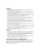
WARNING: • The GMR-GPS should be used as an aid in navigation. The unit is not intended to replace basic navigational procedures and common sense. • Because of errors inherent in the nature of the GPS system, the unit will not guide you to an exact position or the precise indicated coordinates. However, under most circumstances, it should be accurate to within about 100 feet. • When using this device in a vehicle, use it only when the vehicle is stopped and it is safe to do so.
GENERAL FEATURES GPS FEATURES - 128 x 64 Dot Pixel LCD Display - LCD Backlight for Night Operation - Mode Icons for GPS + RADIO, GPS ONLY and RADIO ONLY - 8 Parallel Channel Satellite Receiver - GPS Partner Locator (GP LOCATOR) - Stores 10 Routes with Up to 20 Waypoints Each - Provides 5 Tracks - Map and Pointer Displays Provide: Latitude and Longitude Current/Average/Maximum Speed Bearing and Heading Date and Time Sunrise and Sunset GMRS FEATURES - 15 GMRS Channels (7 Shared FRS) 38 Privacy Codes (For Eac
Generally, the position displayed by a GPS receiver using the C/A signals should be accurate to within 100 feet, and for 50% of the time it should be accurate to within about 40 feet. It is normal for the displayed position to “wander” slightly over time. For the same reason, the altitude displayed by a GPS receiver will also vary slightly. It is important to understand that such variations are inherent in GPS and do not indicate a fault in the receiver.
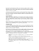
GETTING TO KNOW YOUR GMR-GPS UNIT 3 (TOP) 2 (REF) 4 2 5 1 6 16 7 15 8 14 9 10 13 (BOTTOM) 12 11 1. Push-to-Talk Button (PTT) Button: Used during GMRS radio operation when transmitting voice signals and call tones. 2. Global Positioning System Antenna: Provides reception of GPS satellite signals to determine location. The unit should be held upright to maximize received satellite information. 3. Built-In Speaker: Provides receive audio during GMRS operation. 4.
9. 10. 11. 12. 13. 14. 15. 16. Page Button (PAGE): Scrolls sequentially through menu pages in the forward direction, and also provides access to a shortcut display for easy acquisition of main GPS displays. Battery Compartment Cover: Allows access to four AA batteries when removed. DC6V Jack: It accepts a DC-to-DC vehicle cigarette lighter battery eliminator adapter. Battery Charging Contacts: Provide in-unit charging of batteries when unit is placed in charging stand.
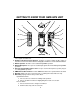
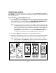
Accessories SPRING CLIPS SUPPLIED: (1) Belt Clip (1) Carrying Case (P/N GMRGPS-CS) OPTIONAL: (1) Desktop Charger (P/N GMRGPS-SC) and AC/DC Wall Adapter (P/N GMRGPS-WA) (1) Vehicle Cigarette Lighter Battery Eliminator (DC12V-to-DC 6V) (P/N GMRGPS-BE) (1) Car Mounting Bracket (P/N GMRGPS-CB) (1) Headset (P/N FRS-BHST) (1) Set of Rechargeable Batteries CLIP RELEASE TAB (PRESS DOWN) SPRING LOADED BELT CLIP Belt Clip Accessory Powering the GMR-GPS Unit: Your GMR-GPS unit operates on four AA batteries.
The following guidelines will improve performance and provide longer operating times for the GMR-GPS unit: 1. Do not mix old and new batteries. 2. The use of alkaline-type batteries is recommended to provide the longest operating time. 3. Do not mix alkaline, standard (carbon-zinc) or rechargeable (NiMH) batteries. 4. If the unit is not to be used for an extended period of time, remove the batteries. Old or leaking batteries can cause damage to the unit and will void the warranty.
OPERATIONAL MODES The GMR-GPS is capable of three modes of operation; namely, RADIO ONLY, GPS ONLY or GPS + RADIO. The desired mode can be selected using the Setup menu once the unit is turned on and in the standby mode. Power On/Off ( ) and Mark (M) Button (14) 1. Press and hold the power On/Off ( ) button for at least 2 seconds. You will hear a confirming beep to indicate the unit is on.
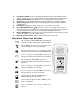
NAVIGATION PAGE STANDBY PAGE PRESS ENTER PRESS ENTER PRESS/HOLD PAGE PRESS/HOLD PAGE MAP PAGE POINTER PAGE PRESS ENTER PRESS ENTER PRESS/HOLD PAGE PRESS/HOLD PAGE PRESS ENTER PRESS ENTER GATEWAY PAGE SETUP PAGE MENU PAGE PRESS/HOLD PAGE PRESS AND HOLD PAGE TO ACCESS GATEWAY DISPLAY FROM ANY PRIMARY DISPLAY PAGE; MOMENTARILY PRESS PAGE TO ACCESS THE NEXT PRIMARY DISPLAY PAGE.
Scrolling Through the Menu Pages: 1. With the unit in the GPS ONLY or GPS + RADIO standby mode, pressing the PAGE button will permit scrolling through the primary radio/GPS menu pages. a. Navigation Page b. Map Page c. Pointer Page d. GPS Menu Page e. Setup Page f. Standby Page 2. With the unit in the RADIO ONLY standby mode, pressing the PAGE button permits scrolling through the radio menu pages. 3.
GMR-GPS Operational Menu Flow Diagram, Figure 1 13 ENTER BASIC SETUP ENTER ENTER PRESS PAGE VERSION NO. ON/OFF OFF/SHORT/LONG SET BETWEEN 1 AND 10 OFF/15 SEC/30 SEC/1 MIN/STAY ON RADIO ONLY (FIG. 4) GPS ONLY (FIG. 2) GPS + RADIO (FIG. 2) PRESS PAGE NAUTICAL/ STATUTE/ METRIC MM-DD-YY/ DD-MM-YY/ YY-MM-DD 12 HOUR/24 HOUR DEFAULT = WGS-84 DDD MM’ SS’/ DDD, DDDDD/ DDD MM.
GMR-GPS Operational Menu Flow Diagram, Figure 2 14 FROM FIGURE 1 GPS ONLY PRESS PAGE GPS ONLY SETUP GPS ONLY STANDBY PAGE NAVIGATION PAGE PRESS PAGE PRESS PAGE PRESS ENTER STATUS PAGE GPS MENU PAGE PRESS PAGE MAP PAGE PRESS ENTER POINTER PAGE PRESS PAGE PRESS PAGE PRESS ENTER
PRESS ENTER PRESS ENTER PRESS ENTER PRESS ENTER GMR-GPS Operational Menu Flow Diagram, Figure 3 15
PRESS PAGE SET DUAL CHANNEL (1-15) OFF/1-9 MELODIES VOX DELAY OFF/ 1-4 SEC ROGER BEEP ON/ OFF ON/OFF PRESS ENTER TO HOT KEY MENUS, FIGURE 5 SETUP MODE FROM FIGURE 1 RADIO ONLY PRESS PAGE PRESS ENTER PRESS PAGE PRESS PAGE RADIO ONLY STANDBY PAGE GMR-GPS Operational Menu Flow Diagram , Figure 4 16
GMR-GPS Operational Menu Flow Diagram, Figure 5 17 ENTER HOT KEY MENU USE UP/DOWN WHEEL KEY TO HIGHLIGHT ITEM; THEN PRESS ENTER NOTE: PRESS ENTER CTCSS SUBCODE SELECT (1-38) THE HOT KEY MENU IS ACCESSIBLE FROM BOTH THE GPS + RADIO STANDBY PAGE AND THE RDO (RADIO) ONLY STANDBY PAGE PRIORITY CHANNEL SELECT (1-15) ALL CHANNEL/ DUAL CHANNEL SCAN SELECT VOX MODE SELECT KEY LOCK ON/OFF SELECT
SETTING UP THE GMR-GPS UNIT After the GMR-GPS unit is turned on, it should be set up and/or tailored for operation according to user specific needs. To accomplish this, the basic SETUP mode must be accessed and the required information needs to be entered. Access the SETUP mode as follows: 1. From either of the GPS Standby modes, press the PAGE button five times ( from the radio only mode press the PAGE button once); the unit should beep each time the button is pressed. 2.
(1) Press Enter; an alphanumeric window appears with a highlighted number/letter corresponding to the character presently being used. (2) Using the Up/Down wheel key, highlight the first ID character desired and press Enter. The first character changes and the cursor moves to the second character position. (3) Repeat step (2) for the second desired character; the cursor moves to the third character position. (4) Repeat step (2) for the third through eighth character , if used; then press Enter.
2. Move the wheel key in the up or down position to increase or decrease the volume setting. The volume bar graph will increase or decrease in steps, accordingly, to a maximum of 16 or a minimum of 1. SETTING UP THE GPS FEATURE Now that the basic setup procedures have been performed, you must now perform the setup procedure for the GPS feature. This is accomplished as follows: 1. From the SETUP display page, select the GPS mode using the Up/Down wheel key; the GPS icon will be highlighted (boxed).
PAGING THROUGH GPS FUNCTIONS INITIALIZING THE GLOBAL POSITIONING SYSTEM MODE Before using the GPS mode of your GMR-GPS unit for the first time, the GPS receiver needs to automatically determine its location. To initialize the GPS receiver, proceed as follows: WATCHING SATELLITE ACQUISITION ON THE GPS STANDBY/STATUS PAGES Your GMR-GPS unit operates on positional data acquired from NAVSTAR satellites. To introduce your unit to this information: 1.
GPS + Radio Standby Page The GPS + RADIO Standby page automatically appears as the default page if the unit is being turned on for the first time, or if it is selected as the operational mode using the SETUP page. In addition to depicting satellite acquisition (SEARCHING/NAVIGATION), this page also displays the following information: 1. A user identification (ID) code consisting of eight characters maximum. If no user ID code appears, refer to basic setup mode. 2. The number of acquired satellites.
UP/DOWN WHEEL KEY GPS Only Standby Page Radio Only Standby Page and Volume Function Radio Only Standby Page The RADIO ONLY Standby page (shown above) can be selected from the SETUP page using the MODE function as previously explained. Unlike the other two modes which include the GPS feature, this standby page depicts a radio only display with the following information: 1. A user identification (ID) code consisting of eight characters maximum. If no user ID code appears, refer to basic setup mode. 2.
PRESS PAGE PRESS PAGE PRESS PAGE PRESS PAGE PRESS PAGE PRESS PAGE PRESS PAGE GATEWAY PAGE ICONS (HIGHLIGHT WITH UP/ DOWN WHEEL KEY AND PRESS ENTER TO ACCESS DISPLAY PAGES) Gateway Page Relationships Hot Key Menu Access A HOT KEY menu is accessible from either the GPS + RADIO or RADIO ONLY standby page; this page appears when the Enter switch is pressed, and provides you with quick access to the basic radio functions. Refer to the section on radio operation for a detailed explanation of these items.
The NAVIGATION Page The NAVIGATION page presents a summary of the important parameters entered into, or computed by your GMR-GPS unit. This page can be accessed from the GPS + RADIO or GPS ONLY standby pages, or it can be accessed from the Gateway menu which is available from any of the pages when operating in the one of the GPS modes.
The Mark (Waypoint) Page Waypoints are the coordinates of user-selected specific geographical or man-made objects along the route you are taking to your destination or endpoint. Geographical objects could be a lake, pond, hill, etc., while a man-made object could be a barn, house, electric tower, etc. Each of these objects along your way can be marked and stored in your GPS unit so that your return path is plainly marked and can be retraced easily.
4. SAVE - When SAVE is highlighted, the coordinates can be saved in memory. In addition, the saved waypoint coordinates can be retrieved using the GPS MENU page and highlighting the WAYPOINTS field. 5. SEND - To transmit the current coordinates, together with user (your) ID, to a remote user GMR-GPS unit tuned to the same channel (and CTCSS sub-code), simply highlight the SEND field and press the Enter switch.
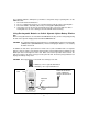
CURRENT LONGITUDE CURRENT LATITUDE ALTITUDE CURRENT TIME HEADING TRAVEL SPEED TRIP TIME ODO (ODOMETER) BEARING DISTANCE TRUE NORTH POINTER PERCENT MEMORY USED BAR MAP PAGE SUB-MENU MAP SCALE PRESS ENTER ANIMATED BOX SYMBOL (YOU) OR QUESTION MARK (LOSS OF TRACK) The Map Page a. AHEAD/NORTHWARD? - When this item is highlighted, press Enter to orient the top of the map display with respect to waypoints or targets ahead of your intended track, or with respect to True North. b.
2. Whether or not the satellite information is sufficient for the unit to provide accurate positional information (SEARCHING or NAVIGATION). The indication provides the level of accuracy of the position based upon the number of satellite signals being received. 3. An information bar at the bottom of the display permits viewing the following parameters when the Up/Down wheel key is used: a. b. c. d. e. f. g. h. i. j. k. l. m. LATITUDE - Degrees, minutes and seconds (dependent on setup selections).
4. When the Enter switch is pressed, a sub-menu appears in the center of this screen, and provides several options related to your trip; these options can be highlighted using the Up/Down wheel key; then press Enter to change the highlighted data: a. AHEAD/NORTHWARD? - When this item is highlighted, press Enter to orient the top of the map display with respect to waypoints or targets ahead of your intended track, or with respect to True North. b.
a. The WAYPOINTS display presents an alphanumeric listing of the waypoints you have marked along your trip. In addition, they appear automatically in numeric order (unless you enter a waypoint ID preceding the waypoint number) as they are marked and entered sequentially. To access the waypoint column, press the Enter switch; the first waypoint group (0-9) will be highlighted.
HIGHLIGHT ITEM; THEN PRESS ENTER PRESS PAGE TO RETURN TO WAYPOINT PAGE Using and Editing the Waypoints During Your Trip 2. ROUTES - Routes consist of at least two or more waypoints that define a path to a destination. This feature guides you from the first waypoint in the route to each successive waypoint until you complete your trip. You can store up to 10 routes. a. From the GPS MENU page, highlight the ROUTES field using the Up/Down wheel key; then press Enter.
HIGHLIGHT ITEM; THEN PRESS ENTER. PRESS PAGE TO RETURN TO ROUTES PAGE Using and Editing the Routes on Your Trip d. This process can be repeated until all the desired waypoints are incorporated into the TRIP route (01) page. e. Whenever a change is made to an item in the route, a MESSAGE display appears when the PAGE button is pressed to return to the ROUTES display. The message reminds you that you have made a change and if you want to save the route. f.
HIGHLIGHT ITEM; THEN PRESS ENTER. PRESS PAGE TO RETURN TO TRACKS PAGE Using and Editing the Tracks on Your Trip a. TRACKBACK - With the TRACKS field of the GPS MENU highlighted, press Enter; The TRACKS menu appears with the first track position highlighted. Using the Up/ Down wheel key, highlight the desired track and press Enter. TRACK LOG LOADING appears momentarily and the memory bar at the top of the screen indicates the percent of track data points remaining to be loaded.
4. GP LOCATOR - The GP LOCATOR field is used to display the coordinates received from other GMR-GPS units or, when the Mark (M) button is pressed, your coordinates are transmitted to another GMR-GPS unit to provide a fix on your location. To access received coordinates, press the Up/Down wheel key to highlight the GP LOCATOR field on the GPS MENU page; then press Enter. The GP LOCATOR menu will appear and will list the ID names, date and time of the individuals who sent their position data to you.
TAKING A TRIAL RUN Now that you are familiar with the GPS page features and what functions they convey, it’s time to take a short trip to test your navigation skills. You’ll need a relatively open area to perform this exercise. Let’s begin by marking your current location; this can be considered a waypoint, so it can be used to guide you to your starting point on your return trip. LET’S BEGIN To begin with, let’s mark your current location as a waypoint.
5. To Change the Location Name: a. On the MARK screen, use the Up/Down wheel key switch to highlight the waypoint name (001, 002, etc.) adjacent to the symbol just changed; then press Enter. The alphanumeric EDIT WAYPOINT NAME screen appears with the first character of the location name highlighted. c. Scroll through the alphanumeric listing using the Up/Down wheel key, and create a name (no more than 6 characters), such as HOME01 or HOTEL1, entering each character (pressing Enter) as it is selected. d.
g. To save the changes, highlight SAVE and press Enter; the new Latitude and Longitude specifying your location are stored in memory; to cancel the changes, highlight CANCEL and press Enter. LETS TAKE A SHORT TRIP Now that the unit knows where you are, press the PAGE button to access the Map page, and let’s take a short trip. 1. Making sure the unit is ready to navigate (satellites acquired), walk at a leisurely pace in a straight line for at least 30 to 50 feet, while observing the Map page.
LOCATING ANOTHER GMR-GPS USER During an excursion with another GMR-GPS user, it is possible to locate this user’s position provided he/she transmits the position, thereby giving you the coordinates of the remote GMRS-GPS unit. To transmit and receive the coordinates, both GMR-GPS units must set to same radio channel number and CTCSS subcode number. By saving these coordinates, you will be able to establish a route to this position using the pointer page compass.
GMR-GPS RADIO OPERATION In addition to its Global Positioning System (GPS) features, the GMR-GPS unit also provides General Mobile Radio Service (GMRS) capability as a hand-held radio transceiver. As a GMRS transceiver, the unit permits radio operation with features such as Coded Tone Controlled Squelch System (CTCSS), Voice-Operated Transmission (VOX), Dual Channel Scan and Key Lock capability.
Releasing the button allows the unit to revert to GMRS standby mode. When receiving an incoming signal, the Monitor icon will be highlighted and depict the relative strenth of the signal. The PTT Button can also be used as a two-way call ringer. Pressing the button twice quickly will call another party on the same channel. The TX icon will be highlighted for approximately 3 seconds and then go out.
EXPLANATION AND USE OF RADIO SETUP FUNCTIONS The radio setup functions, as noted earlier, provide ancillary features, such as Roger Beep, Call Tone, etc. Dual Channel Selection In the RADIO setup menu, the first item listed is DUAL CH. - Highlight this line using the Up/Down wheel key and press Enter. - A menu appears, listing 10 channels (01-10). - Highlight the desired channel using the Up/Down wheel key, and press Enter.
Accessing the Hot Key Radio Operating Modes Once the basic radio parameters have be set up, the GMRS functions can be activated as desired during radio operation; these functions include selection of the primary operating channel (1-15) and CTCSS sub-code (1-38), priority channel scan mode activation, VOX mode activation, and key lock activation. These functions are present on the HOT KEY menu and are accessed as follows: 1.
EXPLANATION OF HOT KEY MENU USE The HOT KEY menu provides an easy and fast method of accessing and enabling the primary radio functions when operating in the GPS + RADIO and RADIO ONLY modes. Priority Channel Selection In order to communicate with other GMRS units, both transmitting and receiving party must be on the same frequency. The radio function of the GMR-GPS has 15 channels (frequencies 1-15) as indicated on the HOT Key page to the right of the CH item, and also on the standby page.
To enable the channel scan mode: - From GPS + RADIO or RADIO ONLY standby mode, press Enter to access the HOT KEY display; use the Up/Down wheel key switch to highlight the scan mode to the right of the SCAN item. Press Enter. - OFF, SEEK or DUAL appears in a popup menu; use the Up/Down wheel key and press Enter to choose the SEEK scan mode from its current condition. When SCAN is in the SEEK mode, the scan icon ( ) appears on the standby page.
Battery Alert When the charge indication bars on the battery icon ( ) begin to disappear on the LCD panel, recharge unit or install fresh batteries. If the batteries are not replaced, the ( ) icon bars will fade and a unique audio tone will sound each time a button or control is pressed; however, no display changes will occur. This condition will warn the user that the batteries must be replaced, or that the batteries must be recharged. Batteries There are three methods of powering the GMR-GPS: 1.
Troubleshooting P R O B LE M N o transm ission w hile pressing P TT button W eak orno signalreceived U nitw illnottransm itselected location w hen M ark (M )button is pressed R eception ofunw anted signals P R O B A B LE C A U S E R EM ED Y W eak batteries C harge orreplace batteries Incorrectbattery polarity Installthe batteries in the directions indicated on battery tray W eak batteries C hange orreplace batteries C hanneland privacy code not setthe sam e as target receiver A djustthe radio
Technical Specifications: General Frequency Range: 15 GMRS Channels (7 Shared FRS) Channel Spacing Privacy Codes Dimensions (W x H x D) (Without Antenna) 462.5500 - 462.7250 MHz 12.5 KHz 38 for each main channel 2.325 in x 5.25 in x 1.625 in 59.1 mm x 133.35 mm x 41.3mm Power Supply Power Source Operating Time (Transmit: Receive: Standby) Alkaline Batteries, AAA (4), 6 VDC Ni-MH rechargeable, AAA (4), 4.
This transceiver complies with FCC regulations for use in the United States of America. Use in other countries may be prohibited or restricted by local regulation. Please check with the local regulating agency before using this device outside the United States of America. Main Channel Frequencies: Channel Freq. MHz Channel Freq. MHz 1 462.5625 9 462.6250 2 462.5875 10 462.6750 3 462.6125 11 462.5500 4 462.6375 12 462.6000 5 462.6625 13 462.6500 6 462.6875 14 462.7000 7 462.7125 15 462.7250 8 462.
Continuous Tone Coded Squelch System Tone Frequencies (in Hz) CTCSS Freq. Hz CTCSS 1 2 3 4 5 6 7 8 9 10 11 12 13 14 15 16 17 18 19 67.0 71.9 74.4 77.0 79.7 82.5 85.4 88.5 91.5 94.8 97.4 100.0 103.5 107.2 110.9 114.8 118.8 123.0 127.3 20 21 22 23 24 25 26 27 28 29 30 31 32 33 34 35 36 37 38 * 00 = No Tone 50 Freq. Hz 131.8 136.5 141.3 146.2 151.4 156.7 162.2 167.9 173.8 179.9 186.2 192.8 203.5 210.7 218.1 225.7 233.6 241.8 250.
90 DAY LIMITED WARRANTY Applies to Audiovox Family Radio and General Mobile Service Products. AUDIOVOX CORPORATION (the Company) warrants to the original retail purchaser of this product that should this product or any part thereof, under normal use and conditions, be proven defective in material or workmanship within 90 days from the date of original purchase, such defect(s) will be repaired or replaced with new or reconditioned product (at the Company's option) without charge for parts and repair labor.
© 2001 Audiovox Electronics Corp.