LCM1331FD / LCM1331FDW Owner’s/Installation Manual 13.3” Flip-Down In Vehicle Entertainment System Audiovox Specialized Applications, LLC 23319 Cooper Dr. Elkhart, IN 46514 219-264-3135 www.asaelectronics.
Features - TFT Active Matrix Color 13.
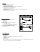
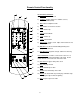
Rear Panel Feature 7 6 4 11 11 5 11 11 12 3 2 8 1 9 10 1) 2) 3) 4) 5) 6) 7) 8) 9) 10) 11) 12) 12 Left RCA Out: Hook-up for left audio out (white female RCA jack) Right RCA Out: Hook-up for right audio out (red female RCA jack) Video Out: Hook-up for video out (yellow female RCA jack) Power Harness Connection: This plug connects to the power harness mating plug Optional Wired Headphone Connections: Green is right positive, Gray is left positive and Black is the ground.
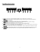
Front Button Panel Features 1 2 3 4 6 5 7 8 9 1) Power: This button turns LCM1331FD/LCM1331FDW on and off. Dimly lit when in stand-by mode. 2) Channel ∆ ∇: Pressing ∆ will select higher programmed channels and pressing ∇ will select lower programmed channels than current channel. 3) Volume ∆ ∇: Pressing ∆ will raise the volume and pressing ∇ will lower the volume. 4) Select: Each press of this button selects the next source (1-3).
General Installation Approach 1) Before beginning installation, please refer to warning on page 10. 2) Decide upon system configuration and options that will be installed (ie: what components, VCP, remote headphones, 2nd VCP, etc.). 3) Review all manuals to become familiar with electrical requirements and hook ups. 4) Decide upon mounting locations of all components and method of mounting.
Vehicle Preparation 1) Locate vehicle power source. Generally this is best found near the vehicle’s fuse block, which is usually (though not always) under the steering wheel area. Locate an accessory hot circuit to tap into video system power. Accessory hot means a circuit that is +12VDC when the ignition key is in either the “ACC’Y” or “Run” positions, and 0 volts DC when the ignition key is removed from the vehicle.
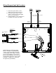
Wiring Diagram Hook Up Procedure Antenna TV antenna (If applicable) 1) Connect the power harness to the mating connector on the video pod. 2) Connect the power harness to the vehicle’s electrical system by tapping into an accessory hot line. 3) Verify all functions of the system before mounting of the finished assembly. Power Harness Item 1 Red: +12 VDC (Accessory Cir.
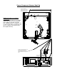
Source Component Harness Hook Up Connect to Mini-DIN connector in area shown. A cable tie may be used in holes provided for strain relief. FM Modulator/Wireless headphone Connections FM Modulator white RCA jacks to red RCA (Right Audio Out) and red or yellow RCA from modulator to red RCA (Left Audio Out). WHPRF01 Wireless Headphones red or yellow to white RCA (Left Audio Out) and wireless headphone white RCA to white RCA (Right Audio Out).
Remote Control Functionality 1 2 TELEVISION CONTROLS: 1) TV Power: Turns unit on/off 3 2) TV/Video: Toggles between 3 available sources; Tuner/VCP/DVD (VCP2) 3) Mute: Mutes headphone audio 4 4) 0-9: Numbers for channel selection 5 5) ∆ CH: Channel Up 6 7 8 6) ∇ CH: Channel Down 7) ∆ Vol: Volume Up 8) ∇ Vol: Volume Down 9) Skip/Search: Toggles on/off.
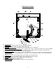
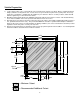
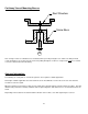
Cut-Away View of Mounting Bosses Roof Structure Screw Boss C3 Note: If longer screws are substituted, care should be taken to prevent piercing the roof, and be sure that pan head screws and washers are used to prevent screws from pulling through the screw boss. Eight screws must be used and secured to solid structure when mounting. Antenna Information The following are a few points to consider in regards to TV reception in a mobile application.
Troubleshooting Symptom: Picture scrolls or is fuzzy Cause: Antenna type or location Poor Reception Vehicle is moving Not receiving certain channels Connections Unit will not respond to remote control Sensor is blocked No power to unit Batteries in remote control are weak Power connection Fuse blown at fuse panel For Installation Help, Call: Audiovox Specialized Applications, LLC 800-688-3135 M-F, 8:00AM –5:00PM EST 11 Possible Solution: Change antenna or try antenna in a different location Vehi
Specifications Video System: NSTC Analog Composite Video (1V P-P, 75Ω) A/V Switching: 3 channels Power: 10-16 VDC, Negative Ground Aux Audio Outputs: Left and Right Variable (800mV max, 8Ω load min.) Left and Right Fixed (300mV typical, 600Ω load min.) Current Consumption (stand-by mode): 67mA Current Consumption (on, but no VCP): 635mA Current Consumption (with one VCP on): 1.5A Audio Noise Floor (30KHz BW): 1.164mV (-58dB re:1V) THD+N @ -10dBV, 1KHz (30KHz BW): 0.
Optional Product List Televisions AVT-988 9” Color Television with Remote (12V) AVT-1498 13” Color Television with Remote (12V) VCP and DVD Players For use with TV’s and LCD AVP-7000 Video Cassette Player (12V) AVP-7285 Stereo Video Cassette Player (12V) Single Disc DVD Player Headphones Wireless Headphones Headphones with Pivoting Ear Cup Headphones with Volume Control on Cord Studio Quality Headphones Miscellaneous Remote Controls Wallmount Family Radio Service with 4 Handsets Replacement Handset 12V Cord
P/N 1281331 Rev.