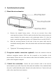
Rearview Mirror with 4.5" Color LCD with Navigation/2 Camera inputs/Compass And Outside Temperature Display Model: LCMR6CT Installation Manual Features: Rearview Mirror with 4.
Cautions! The product is intended to assist in safe driving and to allow the driver to have a broader rearview while the vehicle is in reverse. You, as the driver, are solely responsible for the safe operation of your vehicle and the safety of your passengers according to the country and their local traffic regulations. Do not use any features of this system to the extent it distracts you from safe driving. Your first priority while driving should always be the safe operation of your vehicle.
TABLE OF CONTENTS Cautions! 1 Preface 3 Packing list 3 1.Installation Instructions 4 2.Signal Inputs 7 3.
Preface This replacement mirror /monitor can display up to 3 different video inputs. The inputs are Navigation, Rear observation camera and Interior observation camera. Not all rearview mirrors attach to the vehicle with the same style mount. Please consult the application guide for the appropriate mounting bracket for your vehicle or call Tech Service at 800-225-6074. Packing list The Rear view mirror Model LCMR6CT consists of the following items: 1. Rear View Mirror-1 2. Camera Cable-2 3.
1. Installation Instructions (1) Mount the mirror/monitor a) Remove the original factory mirror. (Do not use excessive force when removing factory mirror.) Check to make sure that the factory mirror mount you remove matches the mirror mount on the replacement mirror. If it does not match, consult the application guide or call Technical Service at 800-225-6074. b) Slide the receiving bracket on the back of the new mirror stalk onto the windshield mounting button.
(4) Installing the Temperature Sensor. a) Select a suitable location for the Temperature sensor outside of the vehicle. The location should be in the nose area of the vehicle, between the front of the radiator and front bumper where there will be airflow. Keep the sensor as low as possible, and as far away from the radiator as possible. b) Use the supplied screw to secure the temperature sensor to the selected location.
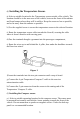
b ) Secure the Compass sensor using the screw provide or double sided adhesive tape to the selected location with the head of the compass sensor arrowhead facing forward. c ) Route the Compass cable up the A pillar and connect the 5 pin Compass Sensor cable to the mating 5 pin connector of the Temperature/ Compass Y cable. d ) Tuck the connectors under the head liner. Figure 3 Note: Compass must be calibrated before use. How to Calibrate the Compass Direction A.
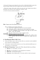
WARNING: Observe polarity when connecting the wires. Control BOX To Control BOX Filter BOX Cam Button Selector Switch To Rearview Camera Red (+12V) Blue (Ignition) Black (GND) Green (Reverse) To Interior Camera To Mirror Assembly To Filter BOX Figure 4 2. Signal Inputs The signal input connections for the system include: (1) Rear Camera: Plug the RJ 11 camera cable end into the control box AVin-1 location, route the cable to the rear camera and plug the 4-pin connector into camera 4 pin connector.
(6) Navigation Image (optional Navigation System required) The Navigation Image is the default mode, and will only be overridden when the vehicle gear selector is moved into reverse, or if the CAM button on the mirror is pressed. Some operators may find that leaving the Navigation Image on the LCD monitor at all times becomes a distraction while operating their motor vehicle. For the convenience of those operators, a ‘Display Timer Slide Control Switch’ has been added to the mirror. A.
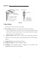
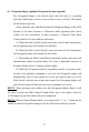
Figure 5 3. Controls and Indicators Figure 3 shows the function controls of the rear view mirror. A: 4.5" LCD Panel B: Rearview Mirror Glass C: “+”Button (optional Navigation System required) Incrementally increase volume level of the navigation voice command when pressed. Note: Will only operate when the Navigation System remote control is removed from the cradle.
E: “MAP” Button (optional Navigation System required) Each time the “MAP” button is pressed, the navigation display will toggle between Map, Icon only and split screen while in navigation mode. Note: Will only operate when the Navigation System remote control is removed from the cradle. F: “-” Button (optional Navigation System required) Incrementally decrease volume level of the navigation voice command when pressed.
Figure 6 Figure 7 N: Calibration Switch: Used to calibrate the compass display.
Specifications General Power Supply 12VDC Power Consumption <12W Current Draw <800mA Video Input 1Vp-p/ 75 Impedance Audio Input <=1V Audio Power Output 0.5W × 1 (16Ω) Operating Temperature Range 0 degrees C to 50 degrees C Display System Screen 4.
Maintenance Though your Rearview mirror requires little care, you can still maintain its condition and performance by following the procedures below. Keep your system away from excessive moisture, extreme heat or cold, and magnetic fields. Keep liquids away from the display and mirror. To avoid damage, do not place external devices or other objects on the top of the mirror. Occasionally wipe the rearview mirror set with a soft, damp cloth.
Troubleshooting Symptoms Solutions 1. 2. The ON/OFF signal light is not on after the car is started? 3. 1. 2. 3. No video signal appears while reversing the car? 4. Check the installation-wiring diagram. Ensure that the parallel red and black line from the control box is connected properly. Check for 12 volts on the blue wire while the ignition on. Check the rearview Camera lens. Check the rearview Camera wiring and connection.
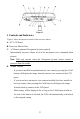
Illustration of Connections Figure 8 15
© 2006 Audiovox Electronics Corp., 150 Marcus Blvd., Hauppauge, N.Y.