MODEL MA200C REMOTE CONTROL MOTORCYCLE ALARM SYSTEM INSTALLATION GUIDE AND OWNERS MANUAL 1
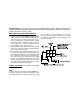
Congratulations on the purchase of your new Audiovox Alarm System. Taking a few minutes to read this installation and owners guide will provide you with the detailed information concerning all the features of your new alarm system. MOUNTING THE SIREN/CONTROL MODULE 1. Choose a location that is away from hot and moving parts considering the Red wire length must be connected to the to the positive terminal of the battery. Prevent access to the siren as much as possible, by mounting in a hidden location.
BLACK (LONG): Using the attached wire lug, connect the Black (long) wire of the siren to the negative terminal of the battery or a good ground source. ORANGE: This wire is used to connect the alarm system to the motorcycle's ignition system Refer to Figure 2. This wire must be connected for the emergency override to function properly in case the transmitter is lost or stolen. When connected to the ignition switch, the wire is connected as is. The wire contains a series resistor.
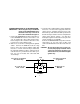
CONNECTING THE RELAY (HORN FEATURE) IMPORTANT! The relay has been shipped with the BLACK wire loaded into terminal 87a of the Relay Socket. The wire must be removed from this location and placed into the outer terminal of the Relay Harness 87. 1. Connect the ORANGE wire from the relay harness to the BROWN/BLACK wire from the main harness. Be sure to insulate this splice with electrical tape. Refer to Figure 4. 2. Gain access to the wires coming from the back of the horn.
3. Locate the wire coming from the starter switch that measures + 12 volts on the logic probe when the starter motor is cranking, and measures 0 volts when the key is switched to the "OFF" position. Cut this wire and try to start the vehicle to verify that the starter motor will not engage. You may also interrupt the ignition circuit of the motorcycle if an electric start wire is not available.
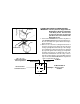
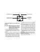
To Bike Harness To Head Lamp Black White/Black 30 85 86 To fused 12V constant source 87a Orange To White wire of siren module 87 FIGURE 6 connection with electrical tape. Connect the WHITE/ BLACK wire to the other side of the headlight wire. 3. Connect both the RED wire from the relay socket and the WHITE/BLACK stripe wire from the relay socket to a + 12 volt battery fused wire (minimum 15 Amp fuse) in the motorcycle.
2. Turn the ignition "ON" then "OFF" 5 times. The system will sound a long chirp to confirm entry into the program mode. 3. Press the "LEFT" button of each transmitter to be programed (up to Two Transmitters). The siren will chirp to confirm each transmitter is now programmed. 4. Turn the ignition "ON" then "OFF" to exit the program mode. The siren will sound a long chirp to confirm the exit from the program mode. bracket and securing the bracket to the motorcycle, are securely tightened.
NOTE: If the alarm issues three warnings within 15 seconds, the siren will sound a regular alarm tone which lasts for 30 seconds. After 30 seconds, the siren will automatically stop and the alarm will arm itself. alarm cycle. At the end of the cycle, the alarm will re-arm itself, and resume monitoring the motorcycle. Disarming the System 1. When you return to the motorcycle, press and release button 2 on the keychain transmitter. The system will respond with two chirps or horn sounds [ two flashes ]. 2.
To activate the panic feature: 1. Press and hold button 1 on the keychain transmitter for 3 seconds. 2. The alarm will sound, and continue to sound for 30 seconds. 3. To silence the alarm before the 30-second shutdown, press and hold button #2 on the keychain transmitter. To use the Override Function: 1.Insert the key into the ignition switch. 2.Turn the ignition switch to the "ON" and "OFF" positions five times within 20 seconds. Each of the five "ON" and "OFF" position changes must be longer than 0.
REPLACEMENT PARTS Replacing the Transmitter Battery The keychain transmitters have a small, red LED visible through the top cover. This LED can be used to indicate battery condition. You will also notice a decrease in effective transmitter range as the battery deteriorates. The replacement battery must be a 12 volt type GP27A or equivalent. Relay Transmitter Battery To replace the transmitter battery: 1.
TROUBLESHOOTING: 3. Verify that the 1 Amp fuse in the red wire from the siren control module is in good condition. Replace it if it is blown. 4. Verify that the connections of the red and black wires have been made according to the wiring section of this manual. Symptom: The Transmitters will not program to the control module. Check: 1. Verify that the 1 Amp fuse in the red wire from the siren control module is in good condition. Replace it if it is blown. 2.
F o r C u sto m e r S e rvice V is it O u r W eb site A t 999.audiovox.com P rod uct In form a tion , P h otos, FA Q ’s O w n er ’s M a n ua ls © 2002 Audiovox Electronics Corp.