Owners and Installation Manual MMD70 7" LCD MONITOR & DVD PLAYER
Note: This Product incorporates copyright protection technology that is protected by method claims of certain patents and other intellectual property rights owned by Macrovision Corporation and other rights owners. Use of this copyright protection technology must be authorized by Macrovision Corporation, and is intended for home and other limited viewing uses only unless authorized by Macrovision Corporation. Reverse engineering or disassembly is prohibited.
Important Notice An LCD panel and/or video monitor may be installed in a motor vehicle and visible to the driver if the LCD panel or video monitor is used for vehicle information, system control, rear or side observation or navigation. If the LCD panel or video monitor is used for television reception, video or DVD play, the LCD panel or video monitor must be installed so that these features will only function when the vehicle is in “park” or when the vehicle’s parking brake is applied.
A. Introduction Thank you for selecting the MMD70. The main features include a 7" Wide Screen (16:9 Aspect Ratio) Liquid Crystal Display (LCD) monitor and a built-in DVD player. The unit applies the latest state of the art electronics. The unit is constructed to provide years of reliable, trouble-free service. Please read the entire instruction manual supplied with this product prior to operation. The documentation will assist you in installing the system properly to obtain the best equipment performance.
. Disc Do not use irregularly shaped discs such as heart or star-shaped discs as they may cause the unit to malfunction. Do not stick paper, tape or glue on the disc. Do not expose the disc to direct sunlight or heat sources such as hot air ducts. Do not touch the surface of disc. Handle the disc by its edge. Clean the disc by wiping the disc from the center out with a cleaning cloth. Remove the disc from the unit and store it in its case after playing.
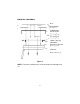
D. INSTALLATION AND POWERING 1. 2. 3. 5. 4. 3 (X 4) (X 2) Figure 1 TOOLS REQUIRED: #2 Philips Screwdriver #1 Philips Screwdriver Utility or Razor Knife or Shears Wire Strippers Upholstery hook tool (for removal of panels as necessary) Electrical Tape Masking Tape Multimeter (to verify 12 volt DC and continuity: Do not use a test light or logic probe) Marker pen – to mark headliner Scribe (to mark trim ring if used) Misc. electrical connectors (to connect to vehicle power source).
GENERAL INSTALLATION APPROACH: 1) Decide upon system configuration and options that will be installed (i.e.: what components, VCP, Tuner, RF Modulator/external amp, remote headphones, DVD, etc.). 2) Review all manuals to become familiar with electrical requirements and hook ups. 3) Decide upon mounting locations of all components and method of mounting.
Notes :The MMD70 video system is only intended for an overhead, drop down installation. It is not intended for seat back or any other type of mounting. The hinging mechanism is designed for horizontal, drop down use only. VEHICLE PREPARATION: 1) Locate an accessory power source (+12v when key is in the ACC. and run positions, and 0v when key is off). Generally, this wire can be found at the ignition switch or fuse-box.
MOUNTING THE MMD70 Figure 2 NOTE: Two of the mounting holes are located under the domelight covers.
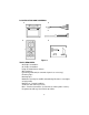
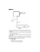
MMD70 (RED) (BLACK) Figure 3 1) Make the connections to the vehicle with the 5 pin wiring harness. 2) Connect the 5 pin harness to the mating connector on the Video Monitor. 3) Connect power harness to vehicle's electrical system by tapping into an accessory hot line. 4) Verify all functions of the system before final mounting of the finished assembly. NOTE: A VCP or other A/V Component can be connected to the video monitor system using an RCA A/V cable.
CONNECTING THE DOME LIGHTS The dome lights in the video monitor require three connections to the vehicle's wiring. There are two common types of dome light circuits used, positive or negative switched. Positive systems supply voltage to the interior lights to turn them on, negative switched systems apply ground to illuminate the bulbs. To determine which system you have you must locate the wires at the dome light.
Positive Switched Dome lighting To constant +12vdc Red / black - Lamp on Black / red - Lamp common Violet / brown - Lamp Auto To 3 pin connector on Monitor Factory Dome light circuit To constant +12vdc Factory Door ajar switch or Body Control computer Figure 4 Negative Switched Dome lighting To 3 pin connector Red / black - Lamp on Black / red - Lamp common Violet / brown - Lamp Auto To constant Factory Dome light circuit To constant Factory Door ajar switch or Body Figure 5 12
E. Controls, Indicators, and Connectors 1.
2.
G.
H. MENU A DVD is divided into sections called titles and chapters. When you play a DVD, a root menu of the disc will appear on the screen of your TV or Monitor. Contents of the menu will vary depending on the disc content. Press MENU during playback to display the main menu. Some DVDs only allow you to select disc playback options using the DVD root menu. I. DISPLAY 1) DISPLAY MODE During playback press DISPLAY to display the current disc playback information. Press display again to remove the display.
4) ANGLE During playback press ANGLE to change the current angle of discs containing muti-angles. (You can see item 8 in Picture 1 change) ‘Angle’ in Display Mode 1/1 ‘Angle’ Display 5) SUBTITLE During disc playback press SUBTITLE* to select the desired subtitle language.(You can see item 12 and 15 in Picture 1 change) 6) AUDIO During disc playback press AUDIO* to select the desired audio language.
7) ZOOM ‘Zoom’ in Display Mode ‘Zoom’ Display During playback press ‘ZOOM’ to enlarge the picture by 2x or 3x with the current zoom multiple displayed.
During playback press ‘REPEAT’ once to repeatedly play the current chapter, press a 2nd time to repeat the current title, press a 3rd time and the repeat function is cancelled and normal playback resumes. Repeat mode sequence:Repeat Chapter/Repeat Title/Off. J. PLAYING AUDIO CDS When playing an audio CD the display will automatically display the disc playback information. The options below show you what information is displayed. Press the ‘DISPLAY’ button to remove the display. 1. The current track. 2.
USING THE REPEAT FEATURE The default mode for the Repeat feature is OFF. Pressing REPEAT consecutively changes the repeat options: • Repeat Single- repeats the track that is playing. • Repeat All- repeats the disc that is playing. • Off As you toggle through the options, the repeat option changes. The selected repeat option loops repeatedly until its turned off. K. PLAYING MP3 DISCS MP3 is a digital audio format.
4. Use the ( NEXT ) button to move to the next song. Press the (PREVIOUS) button to move to the beginning of the song. USING THE REPEAT FEATURE The default mode for the Repeat feature is OFF. Pressing REPEAT consecutively changes the repeat options: • Repeat Single(repeat playback of a song) • Repeat All(repeat playback of all folder) • Off (normal playback) Pressing REPEAT a 3rd time will resume normal playback. As you toggle through the options, the repeat option changes.
M. SETUP Press ‘SETUP’ to display the Main screen of the SETUP Menu on the screen. Press ‘SETUP’ again to exit the SETUP Menu and the unit will resume it’s last playback mode. Main ‘SETUP’ Menu Screen 1) Select ‘LANGUAGE’ page using the LEFT/RIGHT button. ‘Language’ Display Menu a. Select ‘OSD Menu’ using the UP/DOWN button, then press ENTER to enter the submenu. Select the OSD language you desire using the UP/DOWN button, then press ENTER/LEFT to confirm the setting and exit.
b. Select ‘Subtitle’ using the UP/DOWN button, then press ENTER to enter the submenu. Select the ‘Subtitle’ language you desire using the UP/DOWN button, then press ENTER/LEFT to confirm the setting and exit. ‘Subtitle’ Display c. Select “Audio” using the UP/DOWN button, then press ENTER to enter the submenu. Select the audio language you desire using the UP/DOWN button, then press ENTER/LEFT to confirm the setting and exit. ‘Audio’ Display d.
2) Select ‘Video’ Page by using the LEFT/RIGHT button. ‘Video’ Display a. Select ‘TV Display’ using the UP/DOWN button, then press ENTER to enter the submenu. Select the TV display you desire using the UP/DOWN button, then press ENTER/LEFT to confirm the setting and exit. ‘TV Display’ Display * Normal/PS: When the player outputs signal to a normal TV, and a wide picture is shown on the full screen.
b. Select ‘TV Type’ using the UP/DOWN button, then press ENTER to enter the submenu. Select the TV type you desire using the UP/DOWN button, then press ENTER/LEFT to confirm the setting and exit . ‘TV Type’ Display c. Select ‘Angle Mark’ using the UP/DOWN button and then press ENTER to enter the submenu. Choose Angle Mark on or off using the UP/ DOWN button, then press ENTER/LEFT to confirm the setting and exit. ‘Angle Mark’ Display * On: The screen will show angle mark. (*If angle option is available).
d. Select ‘Last Memory’ using the UP/DOWN button and then press ENTER to enter the submenu. Choose Angle Mark on or off using the UP/DOWN button, then press ENTER/LEFT to confirm the setting and exit. ‘Last Memory’ Display *On: The unit will return to the last position on the disc. *Off: The unit will not return to the last position on the disc. e. Select ‘Screen Saver’ using the UP/DOWN button and then press ENTER to enter the submenu.
3) Select ‘Rating’ by using the LEFT/RIGHT button. ‘Rating’ Display Select ‘Password’ using the UP/DOWN button. Input the password (For the first time use 3308)and press ENTER to unlock the unit. Select ‘Rating’ using the UP/DOWN button and press ENTER repeatedly to change the rating level you desire. Use the UP button to return to ‘Password‘ and input either the default password or any new 4 digit password you want and press ENTER. Next time you can use these 4 new digital as your password. Rating:1.
N. Playing a Video Game (Refer to Figure 8) Change the source by pressing the DVD/AV1/AV2 button on the remote. AV2* is from the AV IN port on the side of the unit. AV1 is the RCA connectors on the top of the unit. Figure 8 Connect the A/V output from your game system to the RCA inputs (AV1) or the 1/8 (AV2)* input on the side . Adjust the volume and picture for individual preference. O. Wired Headphones and Wireless headphones (Refer to Figure 8) 1.Optional wired Headphones may be used.
P. Specification Disc format: DVD/CD/MP3 Color system: NTSC/PAL Screen size: 7” Frequency response: 20 Hz to 20 kHz Video output: 1 Vp-p/75 Ohm, unbalanced Audio output: 1.4Vrms/10kOhm Audio S/N: Better than 60 dB Dynamic range : Better than 85 dB Laser: Semiconductor Laser, Wave Length: 650 nm/790 nm Power source: DC 12V Power consumption: 30 W Operating temperature: 5~35°C Storage temperature: -20~60°C (4~140°F) Operating humidity: 10~75% Dimensions (W x H x D): 223 x 165 x 50 mm (8.78” x 6.5” x 1.
12 MONTH LIMITED WARRANTY Applies to AEC Mobile Video Products AUDIOVOX ELECTRONICS CORP. (the Company) warrants to the original retail purchaser of this product that should this product or any part thereof, under normal use and conditions, be proven defective in material or workmanship within 12 months from the date of original purchase, such defect(s) will be repaired or replaced with reconditioned product (at the Company's option) without charge for parts and repair labor.
© 2005 Audiovox Electronics Corp., 150 Marcus Blvd., Hauppauge, N.Y.