MMD11 11" OVERHEAD LCD MONITOR WITH DVD PLAYER Installation Guide
Important Notice An LCD panel and/or video monitor may be installed in a motor vehicle and visible to the driver if the LCD panel or video monitor is used for vehicle information, system control, rear or side observation or navigation. If the LCD panel or video monitor is used for television reception, video or DVD play, the LCD panel or video monitor must be installed so that these features will only function when the vehicle is in “park” or when the vehicle’s parking brake is applied.
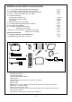
MATERIALS INCLUDED IN THIS PACKAGE: 1) 2) 3) 4) 5) 11" TFT LCD Overhead Monitor With DVD Player 12 Pin Power / Signal harness (P/N 112-3483) 2 Pin Power Wire Harness with choke (P/N 112B3143) 9 Pin ~ 3 RCA Jack Pigtail (P/N 112-3682) Hardware Package Screws ISO 3 x 6mm Long #8 x 3/8" Self Drilling Screws M5 Screws 6) Remote Control (P/N 136-4196) 7) Universal Mounting Bracket (P/N 108-3930) 8) Pry Tool (P/N 100-2424) 9) Trim Ring - Shale (P/N 102-4244) - Pewter (P/N 102-4245) 10) Snap On Cover (Shroud) - S
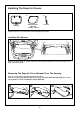
Installing The Snap On Covers 1. 2. 3. Snap On Cover (Shroud) 1 Pewter, 1 Shale Housing Pry Tool Place the pod on a soft surface to avoid damaging the plastic. Installing The Shroud catch catch (A) Begin by hooking area “A” (above) over the dome light and slide the cover over the pod. The cover will snap in place. Removing The Snap On Cover (Shroud) From The Housing Work on a soft surface to avoid damaging the plastic.
GENERAL INSTALLATION APPROACH: 1) Decide upon system configuration and options that will be installed (i.e.: what components, VCP, Video Game, external amp, wireless headphones, VCP, etc.). 2) Review all manuals to become familiar with electrical requirements and hook ups. 3) Decide upon mounting locations of all components and method of mounting.
VEHICLE PREPARATION: 1) Locate an accessory power source (+12v when key is in the ACC. and run positions, and 0v when key is off), and also a good ground generally, these wires can be found at the ignition switch or fuse-box. 2) The mounting method and location will vary from vehicle to vehicle, so this manual will only focus on the installation of the MMD11 and related console accessories. 3) Generally, the best location for the video monitor is where the vehicle's factory dome light is installed.
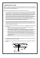
TRIM RING INSTALLATION: Note: This page only covers special installation considerations for thick trim ring installation. If the video monitor is to be installed in a vehicle with the thick trim ring, it may need to be trimmed to fit the contour of the vehicle Head liner. Note: The trim rings supplied with this unit are not designed to be trimmed. 1) In this installation, the video monitor is mounted directly to the overhead cross-member in the roof using the mounting screw bosses.
MOUNTING THE TRIM RING Roof Roof Support Headliner Mounting Bracket Self-drilling Screws Trim Ring Video Unit M5 Screw MMD11 1) Make the connections to the vehicle for the 12 pin wiring harness. 2) Connect power harness to vehicle’s electrical system by tapping into an accessory hot line and a good ground. 3) Connect the 12 pin harness to the mating connector on the Video Monitor. 4) Verify all functions of the System before final mounting of the finished assembly. A/V Source Definitions: 1.
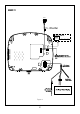
MMD11 AV1 Figure A 9
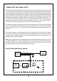
CONNECTING THE DOME LIGHTS The dome lights in the video monitor require three connections to the vehicle's wiring. There are two common types of dome light circuits used, positive or negative switched. Positive systems supply voltage to the interior lights to turn them on, negative switched systems apply ground to illuminate the bulbs. To determine which system you have you must locate the wires at the dome light.
Negative Switched Dome Lighting To 12 pin connector Red / black - Lamp on Black / red - Lamp common Purple / brown - Lamp Auto To constant To constant Factory Door ajar switch or Body Control computer Troubleshooting: SYMPTOM: REMEDY: No power at Video Monitor Verify +12 VDC on Red wire at 2 pin Power Harness behind video monitor.
© 2007 Audiovox Electronics Corp., 150 Marcus Blvd.