INSTALLATION MANUAL VOL/AUDIO PUSH ADJ ON/OFF HEAVY-DUTY VEHICLE ENTERTAINMENT SYSTEM Audiovox Specialized Applications, LLC 23319 Cooper Drive Elkhart, IN 46514 1-800-688-3135 www.asaelectronics.
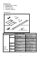
Content List: 1) Nextgen Main Chassis 2) Hardware Kit 3) Wiring Harness 4) Installation Manual Hardware Kit FLANGE NUTS 5 AMP 1 AMP DIN SLEEVE REMOVAL TOOL MOUNTING SCREW 2-Bond Pair From 4-Pin Harness 2-Bond Pair 2-Bond Pair 2-Bond Pair MOUNTING STRAP MOUNTING BUSHING Wiring Color Code Gray Gray/White Orange/White Black Pink Green/White Gray Gray/Blue Gray Gray/Red Gray Gray/Yellow 1 Left Front (-) Left Front (+) Ignition Chassis Ground 12V Out 100mA Memory Right Front (-) Right Front (+) Right R
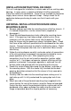
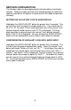
INSTALLATION INSTRUCTIONS- DIN RADIO This unit is designed for installation in vehicle cabs with an existing radio opening. In many cases, a special installation kit will be required to mount the radio to the dashboard. These kits are available at electronics supply stores and car stereo specialist shops. Always check the kit application before purchasing to make sure the kit works with your vehicle.
CAUTION: The rear of the radio must be supported with the strap to prevent damage to the dashboard from the weight of the radio or improper operation due to vibration. INSTALLATION USING KITS 1. If your radio requires the use of an installation kit to mount this radio, follow the instructions included in the kit to attach the radio to the mounting plate supplied with the kit. 2. Wire and test the radio as described in step 3 on page 2. 3.
NEXTGEN CONFIGURATION The Nextgen radio can be programmed to change options and factory settings. Follow the steps outlined in the following pages to modify the radio as required for the options installed and for the mode of operation intended. SETTING THE CLOCK FOR 12 OR 24 HOUR DISPLAY Hold down the AUDIO ADJUST button for greater than 3 seconds. The unit will then enter the general configuration menu. You should see CL24 or CL-12.
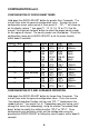
CONFIGURATION con’t. CONFIGURATION OF WORLD BAND TUNER Hold down the AUDIO ADJUST button for greater than 3 seconds. The unit will then enter the general configuration menu. To enter the tuner configuration menu, press preset 4, then preset 2. “CC--**” will show up on the display (where ** can equal 11, 12, 14, 15, 16, or 21). Use the manual “tune up/track forward” button to select the proper country code for the region of interest. The country codes are listed below.
CONFIGURATION- con’t. CONFIGURATION OF TUNER SEEK SENSIVITY SETTING The scan sensitivity feature is designed to give flexibility during the tuner seek function. The tuner can be configured such that during seek, it will stop on strong stations, ignoring weaker signals. The tuner can also be configured to stop at all weak signals. To configure the seek sensitivity setting, hold down the AUDIO ADJUST button for longer than 3 seconds. The unit will then enter the general configuration menu.
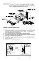
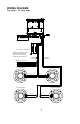
WIRING DIAGRAM See page 1 for color code TO ANTENNA SEE PAGE 4 FOR LOW LEVEL AUDIO INPUT DIN CONNECTOR PINK (TRIGGER) - SEE CHART C *SPEAKER WIRES ARE BONDED PAIRS NEGATIVE GRAY WIRES PAIRED WITH RESPECTIVE POSITIVES *SOLDER AND TAPE ALL SPLICES 4 PIN CABLE CONNECTOR 9 PIN CABLE CONNECTOR BLACK/WHITE (GROUND) GREEN/WHITE (BATTERY +12V) - SEE CHART A ORANGE/WHITE (ACC.
WIRING DIAGRAM – con’t. CAUTION- Connect all speakers before turning the radio on. This radio is designed to operate with a minimum of two speakers. CHART AGreen/White Wire This wire maintains the pre-set memories and clock time. CHART BOrange/White Wire This wire is connected to the “Accessory “ or “On” position of the key switch. The radio will then only operate when the switch is “On” and will automatically shut-off when the key is turned off.
CONFIGURATION- con’t. CAUTION- DO NOT ATTEMPT TO INSERT A CD BEFORE THE RADIO HAS BEEN PROPERLY CONFIGURED FOR CD. THIS WILL CAUSE IMPROPER OPERATION AND MAY CAUSE LOCK UP. IF LOCK UP OCCURS, REMOVE THE CD MECHANISM FROM THE RADIO AND POWER THE UNIT WITHOUT THE MECHANISM IN PLACE. IT IS ALWAYS BEST TO CONFIGURE THE RADIO BEFORE OPERATING A MODULE. CONFIGURATION OF CD MODULE Hold down the AUDIO ADJUST button for longer than 3 seconds. The unit will enter the general configuration menu.
OPTIONAL MODULE INSTALLATION 1. Remove endcaps and loosen front escutcheon screws from the faceplate, carefully removing the faceplate. 2. Carefully remove knockout by un-snapping the top and bottom center clips and discarding the knockout.
INSTALLING THE CD MODULE (NGMCD2) CAUTION: DO NOT INSERT CD UNTIL THE RADIO CONFIGURATION IS COMPLETE! Refer to page 11 configuration instructions. CD1. For installation of CD module (NGMCD2), follow steps 1-3 on page Insert the CD Module into the Nextgen chassis until it clicks in place. CD2. Connect the 14-pin connector from the CD module to the Nextgen chassis on the bottom left corner 14-pin socket. CD3.
CD4. Re-Install faceplate taking care not to pinch wiring from the CD Module chassis. Press the faceplate on the lower bottom center to seat the 18-pin connector before tightening escutcheon screws. Replace endcaps. INSTALLATION OF THE CASSETTE MODULE (NGMMC2) MC1. For installation of the Nextgen Cassette Module, follow steps 1-3 on page 4. Insert the Cassette Module in the Nextgen chassis until it clicks into place. MC2.
MC3. Re-install face plate taking care not to pinch wiring from the Cassette Module chassis. Press the faceplate on the lower bottom center to seat 18-pin connector before tightening escutcheon screws. Replace endcaps. Unlike household electronics, all of our products have been specifically tested for the mobile environment and are only available through ASA. To order any of our products, please contact Audiovox Specialized Applications at www.asaelectronics.com or 800-688-3135.
INSTALLATION NOTES: __________________________________________________________ __________________________________________________________ __________________________________________________________ __________________________________________________________ __________________________________________________________ __________________________________________________________ __________________________________________________________ __________________________________________________________ ____________________
P/N 1282000 Revision E 1/23/01