
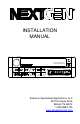
User Guide
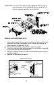
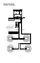
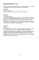
WIRING DIAGRAM – con’t.
CAUTION- Connect all speakers before turning the radio on. This radio
is designed to operate with a minimum of two speakers.
CHART A-
Green/White Wire
This wire maintains the pre-set memories and clock time.
CHART B-
Orange/White Wire
This wire is connected to the “Accessory “ or “On” position of the key
switch. The radio will then only operate when the switch is “On” and will
automatically shut-off when the key is turned off. If a key switched
connection is not possible, this wire may be connected to a constant
+12V source. If this is the case, the radio must be manually turned “Off”
after use to prevent excessive battery drain.
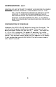
CHART C-
Pink Wire
This wire provides a source of +12 volts only when the radio is turned
on. It may be used to turn on an optional power amplifier (See
instructions provided with the amplifier) or activate an automatic power
antenna to extend when the radio is turned on, if the vehicle is so
equipped. Maximum current draw from the pink wire is 0.1 Ampere, so
do not connect it to accessories that require more than this. Improper
operation or damage may result.
8