PADIN2 Video System Owner’s and Installation Manual Features: -Audio in/out connectors -Full metal chassis -Two microphone input capability with individual gain controls -Internal and external paging capacity -Designed to “trigger”monitors “on” when VCP mode is selected Audiovox Specialized Applications 23319 Cooper Dr.
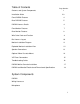
Table of Contents Page Number Contents and System Components Installation Guide 1 2-3 Front PADIN2 Features 4 Rear PADIN2 Features 5 PADIN2 Harness Details 6 Front Monitor Features 7 Rear Monitor Features 8 Wire Color Code and Function 9 Bus Harness Layout 10 Monitor Installation Diagram 11 Exploded Monitor Installation View 12 Speaker Connections 13 Optional Video Cassette Mount 14 VCP Rear Connections 15 Troubleshooting Guide 16 PADIN2 Wall or Console Installation 17 PADIN2
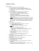
Installation Guide Wiring Precautions 1) To prevent battery discharge or component damage: a) Connect the monitors to 12VDC or 24VDC “Ignition Hot Only” b) Connect PA/Video Cassette Player and Radio to 12V “Ignition Hot Only” c) All monitors have a “trigger” lead (18G Blue/White in monitor pigtail), which is connected to PA. 2) Harness Installation a) For ease of installation, route all cables with vehicle OEM harness. This will reduce the risk of damage to the wiring system.
Installation Guide (cont.) d) Depending on the angle of the luggage rack, a 10°wedge base may be required to keep monitors parallel to the floor. (Fig. 10) e) Drop four 5/16” grade 8 mounting bolts through mounting holes. (from top of luggage rack down) f) Place a mounting plate washer, lock washer, and nut on bolt and tighten to 100 In.lbs. This will provide monitor with a solid mounting base. g) Place a nut, lock washer, and washer on bolt prior to putting mounting bracket in place.
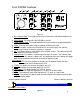
Front PADIN2 Features Figure 2 1) Bass Control Knob- Turn knob clockwise to increase bass and counterclockwise to decrease bass. 2) On/Off Knob- This knob turns the PADIN2 on and off. 3) Treble Control Knob- Turn knob clockwise to increase treble and counterclockwise to decrease treble. 4) Radio- Pressing this button switches between PADIN2 and radio. 5) VCP- This button switches the PADIN2 to VCP and also triggers the monitor. Indicator light will be lit when this function is selected.
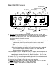
Rear PADIN2 Features Ext. Spkr (-) R Int. Spkr (-) 2 3 4 Radio Input R (+) Radio Input L(+) Audio From VCP (+) R Int. Spkr (+) Ext. Spkr (+) 5 +12V 6 7 1 L Int. Spkr (-) L Int. Spkr (+) IR (+) IR (-) Monitor Trigger Ground Audio From VCP (-) Figure 4 1) MIC Gain- These controls are accessed through the control in rear. The potentiometer marked GAIN1 sets the level for the MIC jack, and GAIN2 sets the level for the second MIC jack.
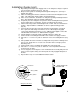
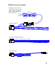
PADIN2 Harness Details IR LED: Clean the IR Receiver window on the front of the VCP, remove adhesive backing and apply IR LED to IR window on the face of the VCP.
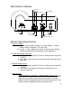
Front Monitor Details 1 Figure 6 1) Power Indicatora) Will illuminate bright red when monitor is triggered “on”by the PA system. b) Will illuminate dim red when monitor is triggered “off”by the PA system.
Rear Monitor Features Video In (-) 12-24VDC 2 Video Out (+) 3 1 Video In (+) 4 Video Out (-) Figure 7 Chassis Ground Trigger From PA 12V Monitor Operating Controls 1) Picture Selectora) “Press”left most button to trigger “On screen display.” Order of control: Contrast, Brightness, Tint and Color. b) Use the “+”and “-“buttons to increase or decrease the setting to achieve the uniformity of each monitor in your application.
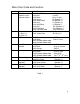
Wire Color Code and Function Number 1 Function PA- Video / Audio Switching and Volume control 2 Front radio Lt. Rear (+) Rt.
Harness Layout 7 7 5 8 7 8 7 6 8 5 3 2 8 5 5 1 1 4 Optional PA location Figure 8 10
Monitor Installation Diagram COMPRESSION PLATES (OPTIONAL) 5/16 x 18 UNC GRADE 8 CARRIAGE BOLTS HARNESS LUGGAGE RACK 1" x 1" VELCRO STRIPS ON 2-SIDES 9" MONITOR WEDGE BASE MOUNITNG BRACKET W/BOLTS 12-24VDC CHASSIS GND TRIGGER VIDEO IN VIDEO OUT MONITOR PIGTAIL 1/4X20 BOLT GRADE 8 4 PLACES 1" x 2" VELCRO STRIPS ON FRONT AND BACK VINYL WRAPPED SHROUD DRIVER SIDE PASSENGER SIDE Figure 9 11
Exploded Monitor Installation View (4) - 5/16x18 UNC Grade 8 Carriage Bolts (P/N 8001500) Compression (Crush) Plate (Optional) (P/N 1400003) Compression (Crush) Plate (Optional) (P/N 1400003) (2) - 1 X 2 Dual Lock Velcro Tape (P/N 8001508) (2) - 1X1 Dual Lock Velcro Tape (P/N 8001508) (4) - 1/4X20X1 Grade 8 Bolts (P/N 8001501) and Washers (P/N 8001503) (12) - 5/16X18 Grade 8 Nuts (P/N 8001030), Washers (P/N 8001502) Lockwashers (P/N 8001504) 10° Wedge Base (Optional) (P/N 1400150) (2) - 1X1 Dual Loc
Speaker Connections To obtain optimum sound pressure level, and compatible load, please use the speaker connection methods illustrated. 18 GRN(+) PASS. SIDE SPKR 18 GRN/BLK (-) 18 GRY (+) 4Ω or 8Ω DRIVER SIDE SPKR 18 GRY/BLK(-) 18 GRN(+) PASS. SIDE SPKR 18 GRN/BLK (-) 4 Ohm only 18 GRY (+) DRIVER SIDE SPKR 18 GRY/BLK(-) 18 GRN(+) PASS. SIDE SPKR 18 GRN/BLK (-) 18 GRY (+) 4 Ohm only DRIVER SIDE SPKR 18 GRY/BLK(-) 18 GRN(+) PASS.
Optional Video Cassette Mount P/N 1401250 (2) Clamp Brackets With 1" Foam Video Cassette Player (1) Mounting Base With 1" Foam Figure 12 14
Rear VCP Connections Figure 13 1) 2) 3) 4) 5) 6) Fuse- 2 Amp Fuse Used Antenna In- External antenna hook-up Video Out- To Monitor or Video Audio Out- To Moinitor or Video RF Out- Channel 3 or 4 output to Monitor Channel Select- Selects setting for channel 3 or 4 selection, depends on area you live in. 7) Power In- Dual input for connection to barrel connector 8) DC 12V- Dual input for connection to 4-pin connector Front VCP Features Figure 14 1) Power- This button powers the VCP “on” and “off”.
Troubleshooting Symptom PA will not power up Cause No 12V power to the PA Monitors will not power up No 12-24V power to monitors Video screens have interference No audio from speakers No 12V trigger voltage from PA to monitor Poor connections Check that PA is set to VIDEO mode Check that PA has 12V power Check crimp connections at monitor Bad VHS tape Dirty heads on VCP Speakers not connected Try new VHS tape Clean VCP heads Measure resistance between gray and gray/black wires (should be between 2-
PA Installation- Wall Mount Lower Left Side Of Driver's Seat PADIN2 DIN Sleeve (4) #8 Self-Tap Screws Wall Can Mounting Plate (Use DIN Sleeve) Wall Mount Box P/N 1400002 (4) #10 Self-Tap Screws ___________________________________________ PA Installation- Console Mount DIN Sleeve PADIN2 Driver's Side Console (4) #8 Self-Tap Screws P/N 8014005 Wall Can Mounting Plate (Use DIN Sleeve) Cut Out 7 1/4" x 2 3/16" 17
PA Electrical and Dimensional Specifications Electrical measurements: *Measurements made at Vcc=14.7VDC Maximum Output Power: 4Ω , Internal Maximum Output Power: 4Ω , External Output Power before clipping: 4Ω , Internal Output Power before clipping: 4Ω , External Output Power, THD 10%: 4Ω Internal Output Power, THD 10%: 4Ω External Signal / Noise Ratio, Input Floated Crosstalk Current Draw, 1/8 rated power all inputs:4Ω Current Draw, (Quiescent) 11.8V (35 Watts) per channel 10.0V (25 Watts) 8.8V (19.
Accessory List Description AVT-988 9” Color Television with Remote (12V) AVT-597 5” Color Television with Remote (12V) AVT-1498 13” Color Television with Remote (12V) AVP-7000 Video Cassette Player (12V) BPA-501-12 4 Amp Adapter for use with AVT-988 9” and AVT-1498 13”Televisions AC2A- 2 Amp Adapter for use with AVT-597 5”TV and AVP-7000 Video Cassette Player Unified Remote Control VAC-21- 12 Volt Corded Vacuum AVF-1 12 Volt Rechargeable Flashlight HP-175 Headphones with Pivoting Ear Cup HP-275 Headphones w