
User Guide
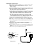
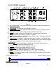


Rear Monitor Features
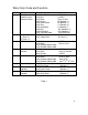
Figure 7
Monitor Operating Controls
1) Picture Selector-
a) “Press” left most button to trigger “On screen display.” Order of
control: Contrast, Brightness, Tint and Color.
b) Use the “+” and “-“ buttons to increase or decrease the setting to
achieve the uniformity of each monitor in your application.
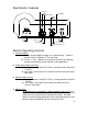
2) Video Input/Output Connector-
a) Mating Connector: Amp P/N 172168-1, Mating terminal: Amp P/N
171637-1.
b) See Table 1 and Figure 8 for customer insertion view and harness
color code.
3) Monitor Power Control-
a) Mating connector: Amp P/N 172167-1, mating terminal: Amp P/N
171637-1.
b) See Table 1 and Figure 8 for customer insertion view and
harness color code.
4) Monitor Fuse-
*Replacement fuse should be a 5 Amp automotive glass fuse* Do
not replace with a higher or lower rated fuse. An over rated fuse will
allow excessive current draw to damage the monitor. An under
rated fuse will fail during power up or cause heat damage to the fuse
holder or monitor (depending on the rating of the fuse).
8
1
Chassis Ground
Trigger From PA 12V
Video Out (-)
Video In (+)
4
3
Video In (-)
2
Video Out (+)
12-24VDC