by AUDIOVOX INSTALLATION MANUAL COMPACT DISC CHANGER SYSTEM MODEL P-150
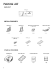
PACKING LIST MAIN UNIT Changer INSTALLATION PARTS Bracket (L) Bracket (R) Hexagonal bolt with washer (M5 x 10) 5 Meter Din Cable 1 pc. 1 pc. 4 pcs. 1 pc. Self-tapping screw (M5 x 12) Seals (A) Seals (B) 4 pcs. 1 pc. 1 pc. OTHER ACCESSORIES 1 CD Magazine Index seal sheet Installation Manual Owner's guide 1 pc. 1 pc. 1 pc. 1 pc.
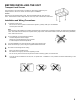
BEFORE INSTALLING THE UNIT Transport Lock Screws The mechanism in the CD changer is "locked" into place during shipment by the transport screws. Be sure to remove the screws prior to installation. Caution After removing the transport lock screws, place the supplied seals (A) over the screw holes. These seals are used to keep dust out of the unit, which could cause a malfunction.
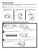
INSTALLATION The unit can be installed horizontally, vertically or at a 45° angle. The position of the built-in anti-vibration springs (left and right side), must correspond to the mounting position chosen. If the springs are not set correctly for the type of installation chosen, the anti-vibration compensation will not be effective and vibration may cause the disc to skip. CAUTION After setting the built-in anti-vibration springs, place the supplied Seals (B) over the holes.
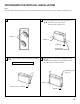
PROCEDURE FOR VERTICAL INSTALLATION Note If the anti-vibration spring position has been changed and verified for vertical mounting (as shown on page 3), start with step 2. 1 Set the 4 anti-vibration springs to position "V". 2 Attach bracket (L) and bracket (R) to each side of the unit, using the hexagonal bolts with washer base (M5 x 8). NOTE: Use seals (A) to cover unused mounting holes on sides of unit.
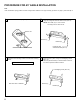
PROCEDURE FOR 45° ANGLE INSTALLATION Note If the anti-vibration spring position has been changed and verified for 45° angle mounting (as shown on page 3), start with step 2. 1 Set the 4 anti-vibration springs to position "45°". 2 Attach bracket (L) and bracket (R) to each side of the unit, using the hexagonal bolts with washer base (M5 x 8). NOTE: Use seals (A) to cover unused mounting holes on sides of unit.
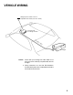
VEHICLE WIRING Mating 8-pin DIN socket on rear of compatible radio chassis (see note 1 below). Car Stereo with CD Changer Controls DIN ca ble (8pin ) CD changer NOTE: 1. Check with your Prestige car audio dealer to be sure your stereo is directly compatible with this CD changer. 2. Wiring instructions for use with FM Modulator/ Commander Systems are included with the P-MC3 and P-MCR4 accessories.
© 1997 AUDIOVOX CORP., HAUPPAUGE, N.Y Printed in Korea Form No.