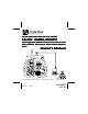
Gener al Mobile Radio Ser vice (GMRS) General Service Model: GMRS-3000PK Rechar g ea ble GMRS Handset T er and Recharg eable Trransceiv ansceiver er W it h N OA A W eat her Trransceiv ansceiver Wit ith NO Weat eather Stt ation T Base S Aler Alertt Owner ’s Man ual Owner’s Manual © 2002 Audiovox Electronics Corp., Hauppauge, NY 11788 Released: 9-6-02.
CAUTION NEVER ATTEMPT TO CHARGE ALKALINE OR DRY CELL BATTERIES, AS BATTERIES MAY BURST CAUSING PERSONAL INJURY AND DAMAGE TO THE PRODUCT. WHEN RECHARGING NICKEL METAL HYDRIDE (NiMH) BATTERIES WITH THE SUPPLIED AUDIOVOX CHARGER AND WALL ADAPTER, USE ONLY AUDIOVOX-APPROVED RECHARGEABLE BATTERIES. USE OF THE AUDIOVOX CHARGER WITH OTHER BRANDS OF BATTERIES IS NOT RECOMMENDED, AS BATTERY CHARGING TIMES WILL VARY WITH DIFFERENT BRANDS.
GMRS-3000PK Handset and Base Station Transceivers The handset transceiver, when equipped with NiMH rechargable batteries, can be recharged when placed in the fixed base station transceiver cradle, which also acts as a desk-top charger.
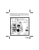
GMRS-3000PK Handset Controls and Indicators 5 (REF) 6 5 7 4 3 8 16 9 15 10 2 1 3 (REF) 14 11 13 12 1 (REF) 17 1. 2. 3. 4. 5. 6. Battery Door Monitor/Backlight Button Detachable Carry Clip Push-To-Talk (PTT) Button Antenna External Speaker(SPK)/Microphone (MIC) Jacks 7. Liquid Crystal Display (LCD) 8. Combination Transmit Indicator (Red)/Receive and Monitor Indicator (Green) 9. 10. 11. 12. 13. 14.
GMRS-3000PK Base Unit Controls and Indicators 6 + DC 9V 5 7 4 8 3 9 10 11 12 13 14 15 2 1 1. Handset Battery Charge Contacts 2. Built-in Speaker 3. Up/Down Channel/Volume Buttons 4. MODE Button 5. Antenna 6. Combination Transmit Indicator (Red)/Receive and Monitor Indica tor (Green)/Backlighting (Red/ Green) 7. DC 9V Charger Input Jack 8. Liquid Crystal Display (LCD) 5 16 17 9. Battery Charge LED (Red) 10. Power On/Off and Function Set Button 11. SCAN/Lock Button 12.
GMRS-3000PK Handset and Base Station Displays 1 9 2 3 10 11 12 13 14 15 16 17 4 5 6 7 8 1. Beep Tone Indicator: Icon appears when beep confirmation tone is selected; icon disappears when tone is off. 2. Monitor Indicator: Icon appears when the Monitor (M) button is pressed and the channel monitor function is activated. 3. Key Lock Indicator: Icon appears when the keypad is locked. This function disables keys such as channel up/down and MODE. 4.
10.Battery Level Indicator: Icon indicates the battery charge level. 11. Emergency (EMG) Indicator: EMG icon appears when the EMG/M button pressed. (The emergency frequency is not monitored by authorities.) 12. Weather Mode Indicator (Base Station Only): This icon appears steady on the Base Station display when the weather mode is active; it flashes when weather alert is active in the GMRS mode. 13.
Powering the Transceivers: Your GMRS-3000PK handset transceiver operates on four AAA batteries. Alkaline batteries will provide slightly better performance than the supplied rechargeable batteries. Only Audiovox approved rechargeable batteries can be recharged in the handset transceiver using the Base Station charging feature and the Wall Charging Adapter supplied with the unit. This will ensure optimum performance for the GMRS-3000PK.
3. Various Brands of Rechargeable Batteries - Use of the Base Station charging feature with other brands of rechargeable batteries is not recommended, as battery charging times will vary with different brands of batteries. Refer to the manufacturer’s instructions for charging other brands of batteries. The battery charge indicator icon displays the battery charge level in the handset transceiver.
Next, press down with the thumb at the embossed arrow on the battery compartment cover, and slide the battery cover down and off the radio. Insert four AAA batteries (alternate positive ends (+) toward the bottom of the transceiver, (starting left-to-right). SPRING LATCH COVER ARROW CARRY CLIP + + POSITIVE TERMINALS BATTERY COVER + + 2. Then lift up cover at 3. bottom to open. Then remove cover from unit.
Base Station Transceiver Charging Setup For the Handset Transceiver When the handset transceiver is equipped with rechargeable NiMH batteries (supplied), they may be charged using the base station setup as follows: 1. Position the handset transceiver in the base station cradle as shown. 2. Connect the charging adapter plug to the DC 9V jack at the rear of the base station transceiver. 3. Plug the other end of the charging adapter into a 120 VAC outlet. 4.
GMRS-3000PK OPERATIONAL MODES HANDSET & BASE STATION MODE Press and Hold MODE Button BASE STATION WEATHER MODE CHANNEL SELECT CHANNEL SELECT CTCSS SELECT WEATHERBAND ALERT POWER SELECT GMRS Channels Only VOX SELECT DUAL WATCH NOTE: ROGER BEEP BUTTON BEEP ID SELECT CALL SELECT The Mode Control features for both the Handset transceiver and the fixed base station transceiver are the same, except the base station also has a Weather Station Alert (NOAA) capability, plus it can charge the Handset batt
Channel/Volume button ( ) to decrease volume. The display will indicate the current volume level between 1 and 7 by the small number in the icon ( U 05 ). Monitor/Display Backlight Button This button is used to check activity on the current frequency before transmitting. Check activity by pressing the Monitor (M) Button longer icon will apppear on the display and you will than 2 seconds; the hear static if frequency is clear. Do not transmit if you hear conversation.
Up Channel/Volume Button In the standby mode, pressing this button will increment the listening volume. When in function edit mode this button will be used to adjust the unit’s settings. Down Channel/Volume Button In the standby mode, pressing this button will decrement the listening volume. When in function edit mode this button will be used to adjust the unit’s settings. Mode Button This button is used to select the various feature settings such as channel/ CTCSS code selection, VOX mode, etc.
- Press and hold the PTT button to transmit, then speak into the microphone clearly and slowly. The Transmit LED lights red. - Release the PTT Button to receive. - Communication can only be accomplished when the channel and CTCSS tone frequency of at least two parties are the same. - The CTC icon will be displayed on the LCD panel if the CTCSS tone frequency function is enabled.
another party on the same main channel using the same subcode. (This filters out unwanted transmissions without the same coded squelch tone). There are 38 CTCSS Sub-channels for each main channel. A different subcode may be selected for each of the 14 channels. To change the CTCSS Sub-channel: - From GMRS/FRS standby mode, press the MODE Button twice; a flashing oF or sub-channel number is displayed, together with the flashing CTC icon.
we do recommend that you not change this setting unless it proves to be necessary in your particular situation. To access the transmitter power selection function, the selected channel must be either GMRS/FRS (1-7) or GMRS only (15-22). Select the desired power as follows: - From GMRS/FRS standby mode, press the MODE Button 3 times until the Po HI or Lo indication appears with a flashing HI or LO indication on the display. NOTE: If the current channel is FRS only (8-14), power will not be selectable.
the unit will resume scanning the two channels. Pressing the PTT button during a received transmission will set the unit to transmit on the same channel. Pressing the PTT button when no signal is received will set the unit to transmit on the primary channel. To set the Dual Watch Mode: - From GMRS/FRS standby mode, press the MODE button 5 times; dc appears on the display with the flashing DW icon. If the dual watch mode is off, the oF icon will also appear flashing.
- Press the Up or Down Button to toggle the key tone feature On or Off. - Press the PTT button momentarily to confirm selection. When the key tone feature is on, the Bell icon appears steady on the display, and the beep tones sound in response to button activation.
the scan is interrupted and will return to scan mode 5 seconds after reception is terminated. NOTE: While the scan function is active, the MODE button will be inoperative. The scan mode will reduce the overall battery life since the battery save function is overridden. To enable the channel scan mode: - From GMRS/FRS standby mode, momentarily press the SCAN But ton; (SCAN) will appear on the LCD display.
To access the Auto Key Lock selection menu: - From GMRS/FRS standby mode, press and hold the Scan Button for over 2 seconds to Lock the Auto Key function; the ( ) icon appears on the display. - The Power, PTT, Up/Down and Monitor Buttons are not effected. - To unlock the Auto Key function, press and hold the SCAN button for at least 2 seconds; the icon ( ) disappears from the display.
- Momentarily press the PTT or Power button to confirm weather channel selection. To exit the Weather standby mode, press and hold the MODE button for at least 2 seconds; the weather alert icon disappears. Weather Alert Mode When the unit is in the weather standby mode and the weather alert is active, when a weather alert signal is received, the unit will generate a warning tone. The unit will then revert to the previously selected weather channel for monitoring purposes.
2. The FRS-3000PK has been designed to maximize performance and improve transmission range in the field. To avoid interference, it is recommended that you do not use the units closer than 5 feet apart. 3. For best transmission results, always keep your mouth about 2-3 inches from the microphone (12, *15) and speak slowly in a normal voice. 4. To increase battery life in the hand-held transceiver, avoid features such as Scan and Dual Watch. These features will reduce operating time considerably.
Troubleshooting Problem Possible cause Correction No transmission while pressing the PTT Button Weak batteries (mobile unit) Incorrect battery polarity (mobile unit) Charge or replace batteries Install the batteries following the directions in paragraph Installing the Batteries.
Technical Specifications: General Frequency Range: Channel 1-7 (Shared with FRS) Channel 8-14 (FRS only) Channel 15-22 (GMRS only) Channel Spacing Privacy Codes Dimensions (W x D x H): Handset Base Unit Power Supply Power Source: Handset Operating Time Duty Cycle: Base Unit Receiver Useable Sensitivity Maximum Audio Output Power Modulation Distortion Transmitter RF Output Power Maximum Deviation Modulation Distortion Refer to Frequency Chart Refer to Frequency Chart Refer to Frequency Chart 12.
Main Channel Frequencies: CHANNEL /TYPE FREQ (MHz ) CHANNEL /TYPE FREQ (MHz ) 1 GMRS/FRS 462.5625 12 FRS 467.6625 2 GMRS/FRS 462.5875 13 FRS 467.6875 3 GMRS/FRS 462.6125 14 FRS 467.7125 4 GMRS/FRS 462.6375 15 GMRS 462.5500 5 GMRS/FRS 462.6625 16 GMRS 462.5750 6 GMRS/FRS 462.6875 17 GMRS 462.6000 7 GMRS/FRS 462.7125 18 GMRS 462.6250 8 FRS 467.5625 19 GMRS 462.6500 9 FRS 467.5875 20 GMRS 462.6750 10 FRS 467.6125 21 GMRS 462.7000 11 FRS 467.
Weather Channel Frequencies: Channel Channel Freq. MHz Freq. MHz 1 2 3 4 162.550 162.400 162.475 162.425 6 7 8* 9* 162.500 162.525 161.650 161.775 5 162.450 10* 163.275 *Canadian Marine CTCSS Tone Frequencies (in Hz) CTCSS Freq. Hz CTCSS 1 2 3 4 5 6 7 8 9 10 11 12 13 14 15 16 17 18 19 67.0 71.9 74.4 77.0 79.7 82.5 85.4 88.5 91.5 94.8 97.4 100.0 103.5 107.2 110.9 114.8 118.8 123.0 127.3 20 21 22 23 24 25 26 27 28 29 30 31 32 33 34 35 36 37 38 Freq. Hz 131.8 136.5 141.3 146.2 151.4 156.
90 DAY LIMITED WARRANTY Applies to Audiovox Family Radio and General Mobile Service Products. AUDIOVOX CORPORATION (the Company) warrants to the original retail purchaser of this product that should this product or any part thereof, under normal use and conditions, be proven defective in material or workmanship within 90 days from the date of original purchase, such defect(s) will be repaired or replaced with new or reconditioned product (at the Company's option) without charge for parts and repair labor.