Model PRO-9675FT Installation Manual 4 Channel Remote Car Starter With Full Feature Alarm System Installation Instructions This Unit Is Intended For Installation In Vehicles With 12 Volt Negative Ground Electrical Systems, Gasoline or Diesel With True Tach Reference And Automatic Transmissions Only.
The PRO-9675 Remote Start/Alarm System is designed to be used with Automatic Transmission Vehicles Only! The unit provides a selectable ignition control that allows a 10 second output for glow plug pre-heat which may be required for certain diesel vehicles, (see selectable feature #9). If the diesel engine has a instant fire, (no glow plug pre-heat system), feature #9 should remain in the default Gasoline mode setting.
chosen location to insure that the drill will not penetrate any existing factory wiring or fluid lines. Carefully drill a 1/4" hole in the desired location and pass the connector end of the LED through the hole and toward the control module. Press the LED firmly into place until it is fully seated in the mounting hole. THE RECEIVER/ANTENNAASSEMBLY: The Superheterodyne Receiver Antenna Assembly provided with this unit allows routing from below the dash board for maximum operating range.
The PRO-9675 is to be used in vehicles with AUTOMATIC TRANSMISSIONS only! Although this combination Alarm/Remote Start unit is a sophisticated system with many advanced features, IT MUST NOT be installed into a vehicle with a manually operated transmission. Doing so may result in serious personal injury and property damage. IMPORTANT! DO NOT PLUG THE SIX PIN MAIN POWER HARNESS OR THE MULTI PIN INPUT / OUTPUT HARNESS INTO THE CONTROL MODULE UNTIL ALL CONNECTIONS TO THE VEHICLE HAVE BEEN MADE.
Yellow Start Wire Detail BLUE Wire: Ignition 1 Output Connect this wire to the ignition 1 wire from the ignition switch. This wire will show +12 volts when the ignition key is turned to the to the "ON" or "RUN" and the "START" or CRANK" positions, and will have 0 volts when the key is turned to the "OFF" and "ACCESSORY" positions. For Diesel Applications, this wire must be connected to the ignition circuit that powers the glow plugs if the vehicle requires glow plug pre-heating.
WIRING CONNECTIONS: Multi Pin Accessory Input/Output Harness White w/ Red Trace Wire: Parking Light Flasher Feed This wire is the common contact of the on board parking light flasher relay. If the vehicle you are working on has +12 volt switched parking lights, connect this wire to a fused + 12 volt source. (Max. 15 Amps) NOTE: If the vehicle's parking lights are ground switched, connect this wire to chassis ground.
Purple Wire: (+) Door Trigger Input If the vehicle's door courtesy light switches + 12 volts when the door is opened, (Some Fords and some Imports), you must connect this wire to the positive output from one of the vehicle's door pin switches. In most cases, the Purple wire will need to be connected to only one door switch no matter how many doors the vehicle has as most door lighting circuits are wired in parallel.
Light Blue Wire: Ignition 3 Output This wire provides a 300mA ground output that becomes active 3 seconds before the Remote Start Unit initializes, and remains grounded while running plus an additional 4 seconds after the Remote Start Unit turns off. In all of the applications described below, a relay will be required. The Light Blue wire can be used to accommodate the following situations: A.
Green w/ White trace Wire: Entry Illumination Ground Output This wire provides a 30 second ground output (300 mA Max.) whenever the remote is used to disarm the alarm or to unlock the doors and provides a continuous pulsed output whenever the alarm is triggered. This wire should be connected to an external relay, and wired to the vehicles interior entry lighting whenever the optional Interior Illumination circuit is desired. See below for relay wiring details.
Orange Wire: Ground When Armed Output This wire provides a 300mA ground output when the alarm circuit is armed to control the starter inhibit relay. Connect the Orange wire to terminal #86 (orange wire) of the relay provided. Connect terminal #85 (red wire) of the relay to an ignition wire in the vehicle that is +12 volts when the ignition switch is turned to the on and start positions and off when the key is off.
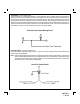
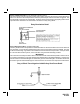
Black Wire: Chassis Ground Source Connect the Black wire to a known vehicle ground source or to a solid clean metal part of the chassis. Be certain to remove any paint or grease and secure this wire with a self taping screw and ring terminal. Chassis Ground Connection Detail Green w/ Orange Trace Wire: Tachometer Input Signal This wire will continually monitor the engine tach rate while the unit is under power of the Remote Start module.
Dark Blue Wire: Delayed 300mA Pulsed Channel 2 Output The Dark Blue wire supplies a 300mA ground pulsed output whenever channel two of the receiver is accessed. Pressing the pre-programmed transmitter button for three seconds will access channel two. This is a low current output and must be connected to a relay to supply power to the trunk release or the circuit you wish to control. Connect the Dark Blue wire to terminal # 86 of a VF45F11 P&B relay or equivalent.
Typically this output will be used to re-lock the vehicle doors if the doors unlock automatically when the ignition circuit transitions to off. Black w/ Yellow Trace Wire: Ground Output During Start (Crank) The Black w/ Yellow Trace wire will provide a 300 mA ground output while the starter output of the remote start unit is active. This output can be used to activate the Crank Low/Bulb Test wire found in some GM vehicles. This wire is also referred to as the ECM wake up wire in some Chrysler vehicles.
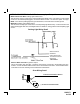
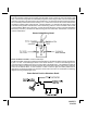
3 Wire Ground Switched Door Lock/Unlock Wiring Detail To Red Lock Wire Of Control Module To Green Unlock Wire Of Control Module 3 Wire Positive Switched Door Locks: In this application, the Red wire of the two pin harness provides a + 12 volt pulse during the disarming sequence, or pulsed 12 volt unlock output. Connect the Red wire to the low current 12 volt signal wire from the factory door unlock switch to the factory door unlock relay.
To Program The Alarm's Selectable Features: Action Turn the ignition switch on Flip the valet/program switch on then off 3 times Within 3 seconds, turn the ignition switch off and then on. First System Response No Response 1 Chirp-LED 1 Flash Short Chirp, then Long Chirp LED Flash Pattern 1 Chirp = 1 second Locks 2 Chirps = 3.5 second Locks 3 Chirps = 1 Second Lock & Double 1 Second Unlock 1 Flash Pause etc. 2 Chirps = auto locks off 1 Chirp = auto locks on 2 Flash Pause etc.
REMOTE START SELECTABLE FEATURES RF Programmable Features: Feature Selection First Second Third Fourth Fifth Sixth Seventh Eighth Nine Ten Park Lights Flash 1 x RF start chirp confirm off 10 minute run time Parking lights on steady (No function) (No function) Ignition 2 off during crank Diagnostics off (No function) Gasoline Engine Starter Pole 5X Park Lights Flashes 2 x RF start chirp confirm on 15 minute run time Parking lights flash Tach operation (No function) Ignition 2 on during crank Diagnostics on
3. 4. 5. 6. 7. Flip the valet/program switch On, Off, On, Off, On, then Off. Siren will chirp once. Immediately turn the ignition key Off. One long siren chirp. Flip the valet/program switch On, then start the vehicle using the key. When the unit senses the tach signal, the parking lights will begin to flash. Flip the valet/program switch Off, The parking lights will turn on for three seconds to indicate that the learned tach signal is stored and the unit is out of the tach learn mode.
TESTING YOUR INSTALLATION: CAUTION!! The following procedure must be performed after the installation of an Audiovox Remote Start Device. It is the responsibility of the installing technician to complete these tests. Failure to test the unit in the following manner may result in personal injury, property damage, or both.
CAUTION! REMEMBER TO RECONNECT THE BROWN/BLACK WIRE TEMPORARILY DISCONNECTED IN STEP 3 MECHANICAL NEUTRAL SAFETY SWITCH CONSIDERATIONS: Mechanical neutral safety switch configurations differ slightly in that they do not offer the same level of safety when installing a remote start device.
KEY IN SENSOR CIRCUITS: If the vehicle you are working on does not have or you cannot locate the ECM reference wire, there are two alternatives available. Although not preferred, the vehicle Key In Sensor may be reconfigured to allow a margin of safety and will prevent the vehicle with a Mechanical Neutral Start Switch from starting in gear. AUDIOVOX ADVISES THAT YOU MAINTAIN THE FACTORY CIRCUIT WHENEVER POSSIBLE. The following two circuits may be used only if the above circuit is not available.
METHOD 2 To connect to the key in sensor circuit as shown for method 2: A. Locate the control wire that connects the drivers door pin switch to the key in sensor switch. B. Cut this wire and connect the ignition cylinder side to chassis ground. C. Locate the key in sensor switch wire that connects the chime module to the ignition cylinder . D. Cut this wire and connect the ignition cylinder side to the Remote Start Negative Safety Shut down Wire Gray/Black, using a 4002 series diode as shown above.
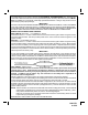
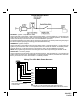
WIRING DIAGRAM © 1998 Audiovox Corporation, 150 Marcus Blvd.., Hauppauge, N.Y. 11788 Form No.