
Installation Manual

128-9324
3 of 12
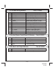
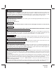
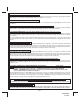
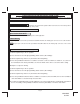
2 Pin Door Lock Output Harness Part #1122242
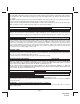
14 Pin Main Wiring Harness Part # 1123895
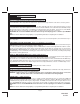
5 Pin Arm/Disarm Trunk Shunt I/O Harness Part #1123237
Page 3
1
Red (+) 12 Volts Parking Light Input
2
White
(+) Parking Light Output 15A Max
3
Red/White + 12 Volt Module Input
4
White/Black (+) Positive Siren Output
5
Purple Positive Door Trigger Input
6
Yellow Ignition Input Switched +12 Volts
7
Green/White Illumination Entry Output (-) 300mA
8
Black/White Horn Output (-) 300mA
9
Black Chassis Ground
10
Orange Ground Output While Armed (-) 300mA
11
Brown Negative Door Trigger Input
12
LT. Green Negative Trigger Input Zone 1
13
DK. Green Negative Hood / Trunk Trigger Input
14
Green/Black Auxiliary Output (-) 300mA
1
Green/Black Arm 2 Input
2
Red Disarm 1 Input
3
Green Arm 1 Input
4
Red/Black Disarm 2 Input
5
Blue Trunk Shunt Input
1
Red Neg. Lock / Pos. Unlock 300mA Max
2
Green Pos. Lock / Neg. Unlock 300mA Max.