Model PRO9644E Install Manual Table Of Contents: Before You Begin Wire Harnesses Quick View Mounting Of The Major Components 6 Pin Power Connector 14 Pin Main Wiring Connector 2 Pin LED / Valet Switch Connectors 4 Pin Shock Sensor Connector 3 Pin Door Lock/Unlock Connector & Wiring 4 Pin Upgrade Telematic Module Completing The Installation Dome Delay Learning Proceedure Adjusting The Shock Sensor Final Steps Wire Dressing and Operation Explanation Programming Bank 1 (Transmitters) Programmi
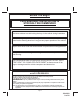
Before You Begin PROFESSIONAL INSTALLATION IS STRONGLY RECOMMENDED Roll down window to avoid locking the keys in the vehicle during installation. Avoid mounting components or routing wires near hot surfaces or near moving parts like the steering wheel as it may prevent proper operation of the vehicle. Tape or loom wires under the hood and dash for protection as well appearance. Use grommets when routing wires through metal surfaces to prevent chafing and shorting.
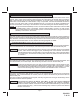
14 Pin Main Wiring Harness 1 Black/White 2 LT. Green 3 NA 4 Brown 5 DK. Green 6 Purple 7 Orange/White 8 Yellow 9 White/Blue 10 Green/White 11 LT. Blue/Green 12 DK. Blue 13 Green/Black 14 DK.
MOUNTING OF THE MAJOR COMPONENTS Control Module: Part # 1365425 Select a mounting location inside the passenger compartment ( up behind the dash ), and secure using the two screws or cable ties. Do Not mount the control module in the engine compartment, as it is not waterproof. You should also avoid mounting the unit directly onto factory installed electronic components. These components may cause RF interference, which can result in poor transmitter range or intermittent operation.
WIRING THE SYSTEM 6 Pin Power Connector: P/N 1124297 Red/White (5 Amp) & Red Fused (15 Amp) Wires : +12 VDC Constant Battery Source This wire supplies power to the alarm's control module as well as the input to the parking light relay. Connect this input to a constant on +12 Volt supply. Orange Wire: 300 mA Ground Output When Armed This wire is provided to control the starter cut relay. Connect the Orange Wire to terminal #86 of the relay.
2 Light Green Wire: (-) Instant Trigger Zone 1 This is an instant on ground trigger input intended for the connection of optional triggering devices. The ground trigger output wire of motion detectors, microwave detectors, or glass break detectors, can be connected to this Light Green trigger input wire.
9 White w/ Blue Trace Wire: Low Current (-) Ground Headlight Output The White w/ Blue Trace Wire is provided to operate the optional headlamp illumination feature of the system. This is a low current (300mA) output and must be connected to an external relay to control the high current switching circuit of the vehicle's headlamps. To use this option, Connect the White /w Blue Trace Wire to terminal #86 of a P&B VF45F11 relay or equivalent.
14 Dark Blue w/Black Trace Wire: Alternate Channel 3 Output (Dbl. Push Required) This wire is controlled from the transmitter button programmed to the receiver's channel 3. By double pressing this the transmitter button, this output will become active for 1 second. This is a transistorized, low current (300 mA) output, designed to provide an output only when the transmitter is intentionally operated, such as is the case with remote start add on modules.
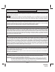
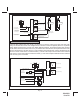
85 Unlock 87a 87 Lock Factory Lock Relay 30 86 From Fuse Box + 12 Volts 86 87a 87 To Red Lock Wire Of Control Module Factory Unlock Relay To Green Unlock Wire Of Control Module 85 30 3 Wire Ground Switched 2 Step Door Locks In this application, the Red Wire provides a ground pulse during arming or locking, connect the red wire to the wire that provides a low current ground signal from the factory door lock switch to the factory door lock control relay.
85 Unlock 87a 87 Lock Factory Lock Relay Drivers Door Motor 30 86 Passenger Door Motors From Fuse Box + 12 Volts 86 To Red Lock Wire Of Control Module 87a 87 Factory Unlock Relay To Red/Black 2nd Unlock Wire From Control Module X 30 85 Cut Drivers Door Unlock Motor Wire Fused + 12 Volt Source To Green Unlock Wire Of Control Module 86 87a 85 If Factory Switches + 12 Volts Connect to Fused + 12 Volt Source. If Factory switches Ground, Connect To Ground.
3 Wire Positive Switched 2 Step Door Locks Connect the DLVI as mentioned above, or use relays to invert the negative output pulse from the 3 pin connector Red & Red/Black to control the lock & all door unlock functions by properly arranging the relay contacts to pulse the vehicle's lock wire, and unlock wire respectively. For the driver priority unlock, if the vehicle does not have a separate drivers door relay, one will have to be added.
4 Pin Upgrade Telematic Module: Red = + 5 Volts Black = Ground White = Data TX Yellow = Data RX Connect the 4 pin harness found in the Telematic one way module kit to the mating port on the telematic module and the other side to the connector on the alarm or keyless entry module. NOTE: I f using the TWO WAY Telematic module, only Ground, TX, and RX are used on this port, the +12 Volt supply for the two way module must be sourced separately or the unit will not operate.
Wire Dressing: Always wrap the alarm wires in convoluted tubing, or with a spiral wrap of electrical tape. Secure these looms along the routing using cable ties. This will ensure that the alarm wires are not damaged by falling onto hot or sharp moving surfaces in the vehicle. Operation: Take a few moments to check off the appropriate option boxes in the owner’s manual, and to fully explain the operation of the system to your customer.
PROGRAMMING BANK 1 (TRANSMITTERS): 1. Turn the ignition key to the on position. 2. Press and release the valet/programming switch 3 times (Siren Chirps). 3. Press the Lock Button of each transmitter you want programmed until you hear a chirp from the horn or siren. 4. Turn the ignition switch off. The above action programs the Lock, Unlock, Start/Trunk, and Option 1 buttons of the system.
Page 15 128-9318 15 of 16 SELECTABLE FEATURES If Programming via PC while connected to +12 VDC you must manually enter the programming mode as shown below: 1. Turn the ignition on. 2. Press and release valet switch 3 times. 3. Turn ignition off then on, off then on, off then on, off then on to enter web/on-line feature selection Bank 5. Siren chirps 5 times indicating access to feature program mode. 4.
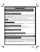
Connector For Telematic Unit When Used Red = (-) Lock Green = (-) Unlock Red/Black = (-) 2nd Unlock Pushbutton LED Assembly PRO9644E Antenna Wire, Route As High As Possible And Away From Other Electronic Modules For Best Range Red (+) Black ( Ground) Green ( Full Trigger) Blue (Pre Detect) To Shock Sensor Red/White (+) 12 VDC 15A To FlashLogic Module When Used 5A White Parking Light Output (+) Black (Chassis Ground) Red (+) Parking Light Input Orange (-) Output To Starter Inhibit Relay White/Black