
Installation Manual


128-9318
12 of 16
Page 12
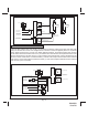
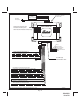
4 Pin Upgrade Telematic Module:
Red = + 5 Volts
Black = Ground
White = Data TX
Yellow = Data RX
Connect the 4 pin harness found in the Telematic one way module kit to the mating port on the telematic
module and the other side to the connector on the alarm or keyless entry module.
NOTE: If using the TWO WAY Telematic module, only Ground, TX, and RX are used on this port, the
+12 Volt supply for the two way module must be sourced separately or the unit will not operate.
COMPLETING THE INSTALLATION
NOTE: This unit has the ability to learn the dome light delay time, up to 60 seconds. If the vehicle
has delay interior lights, and you wish to avoid three chirp, defect zone, indication normally
associated with this type of interior light, we suggest you learn the interior light delay.
TO LEARN THE DOME LIGHT ENTRY DELAY START WITH ALL DOORS CLOSED:
1. Use the transmitter to Lock / Unlock / Lock / Unlock / Lock / Unlock / Lock, the system. The LED
turns on solid to conrm the system entered the learn mode.
2. Immediately open and close the door of the vehicle to initiate the dome delay. The unit will monitor
the door trigger input Positive, (Purple), and Negative, (Brown) when active. When the dome light
turns off, the unit will add 2 seconds then exit the learn mode.
3. The LED will begin ashing the Armed indication indicating the unit has exited the learn mode and is
armed.
Antenna Wire:
Be sure to extend the thin black antenna wire to its full length, and cable tie into place where it cannot
be damaged. Avoid wrapping this wire around major, high current wire looms.
Adjusting the Shock Sensor: P/N AS9492A
If used, the sensitivity of the pre - detect circuit is automatically set 30% less sensitive than the full trigger
circuit.
Using a small screwdriver, gently turn the adjustment screw fully counterclockwise. (DO NOT over turn
this screw. Maximum rotation for this adjustment is 270°). Close the hood and trunk lids, and arm the
alarm. Wait 6 seconds for the accessories trigger zone to stabilize, then rmly strike the rear bumper with
the side of a closed st considering the amount of force required to break a window.
WARNING: Never perform this test on the vehicle’s glass, as you may break the window. Turn the
adjustment screw clockwise (increasing sensitivity) about ¼ turn and re-test. Repeat this
procedure until the alarm sounds. Ultimately, one rm strike to the rear bumper will cause
the alarm to emit pre-detect warning tones.
CAUTION: Setting the sensitivity too high can cause false alarms due to noise vibrations from passing
trucks and heavy equipment. To decrease sensitivity, turn the adjustment screw counter
clockwise.