
Installation Manual


128-9318
4 of 16
Page 4
MOUNTING OF THE MAJOR COMPONENTS
Control Module: Part # 1365425
Select a mounting location inside the passenger compartment ( up behind the dash ), and secure using
the two screws or cable ties.
Do Not mount the control module in the engine compartment, as it is not waterproof. You should also
avoid mounting the unit directly onto factory installed electronic components. These components
may cause RF interference, which can result in poor transmitter range or intermittent operation.
Siren: Part # AS9903E
Select a mounting location in the engine compartment that is well protected from access below the vehicle.
Avoid areas near high heat components or moving parts within the engine compartment. To prevent water
retention, the ared end of the siren must be pointed downward when mounted.
Mount the siren to the selected location using the screws and bracket provided.
Hood or Trunk Pin Switch: (Optional) Part #1363699
An optional pin switch should be used for protecting the hood or trunk (or hatchback ) of the vehicle. The
switch must always be mounted to a grounded, metal surface of the vehicle. It is important to select a
location where water cannot ow or collect, and to avoid all drip gutters on hood and trunk fender walls.
Choose locations that are protected by rubber gaskets when the hood or trunk lid is closed. The pin switch
can be mounted using an optional bracket or can be directly mounted by drilling a ¼“ diameter mounting
hole. Keep in mind that when properly mounted, the plunger of the pin switch should depress at least ¼“
when the hood or trunk lid is closed.
Pushbutton LED Combination Switch: Part # PBLED
Select a mounting location known and accessible to the operator of the vehicle. A dashboard plug or
front dashboard panel is desirable because the pushbutton LED assembly needs the LED to be visible
from the outside of the vehicle. It will be used for valet modes, programming features, programming
transmitters, and for overriding the system when the transmitter is not functioning. Inspect behind the
chosen location to insure that adequate clearance is allowed for the body of the switch, and also that the
drill will not penetrate any existing factory wiring or uid lines. Drill a 5/16" or 8mm hole in the desired
location and mount the switch by passing the connectors, one at a time, through the panel from the front
side and pressing on the bezel until the switch is fully seated.
Shock Sensor: Part # AS9492a
Select a solid mounting surface for the shock sensor on the rewall inside the passenger compartment,
and mount the sensor using the two screws provided. The shock sensor can also be secured to any xed
brace behind the dash using tie straps.
Whichever mounting method is selected, make certain that the sensitivity adjustment is accessible for
use later in the installation.
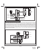
STARTER INHIBIT RELAY: Part # 1363731
Select a mounting location within 12" of the ignition switch's low current start solenoid wire. Secure the relay
to an existing harness in the chosen location using a cable tie around the relay's wiring harness.
Wire the relay as per the diagram found later in this manual.
CAUTION! Do not wire tie the metal bracket to an existing wiring harness as vibration may cause chafng
and shorting damaging the factory wiring. If an existing harness is not available then secure
the relay's metal mounting tab to an under dash metal brace with a #8 self tapping sheet metal
screw. Wire the relay as per the diagram found later in this manual.