
Installation Manual


128-9318
8 of 16
Page 8
14 Dark Blue w/Black Trace Wire: Alternate Channel 3 Output (Dbl. Push Required)
This wire is controlled from the transmitter button programmed to the receiver's channel 3. By double
pressing this the transmitter button, this output will become active for 1 second. This is a transistorized,
low current (300 mA) output, designed to provide an output only when the transmitter is intentionally
operated, such as is the case with remote start add on modules. If you require more than 300mA drive
from this output, you must drive an external relay coil, and arrange the relays contacts to preform the
specied function.
NOTE: Pressing the transmitter button, then immediately pressing and holding it will cause this output
to be active as long as the transmitter button is depressed.
2 Pin White Connector: DASH MOUNTED LED.
Route the red and blue wires in the 2 pin white connector from the LED to the control module, and plug
it into the mating white connector on the side of the module.
2 Pin Blue Connector: PUSH BUTTON VALET SWITCH P/N PBLED
Route the black and gray wires in the two pin blue connector from the push button valet switch to the
control module and plug it into the mating connector on the side of the module.
4 Pin White Connector: SHOCK SENSOR P/N 1122591
Route the red, black, blue, and green wires in the 4 pin white connector from the shock sensor to the
control module, and plug one end into the shock sensor, and the other end into the mating white connector
on the side of the module.
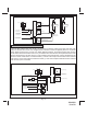
Red, Green, & Red / Black 3 Pin White Connector: Door Lock Outputs P/N 1122906
The Red and Green & Red/Black Wires provide a pulsed ground output to the factory door lock control
relay. The maximum current draw through these outputs must not exceed 300 mA. The Red w/Black
Trace Wire will provide an output when the unlock button of the transmitter is pressed a second time after
a rst unlock command was issued. This is used for second step unlock or all doors unlock in a two step
circuit. In this arrangement, Green is used to control the drivers door unlock relay, and the Red/Black
Wire will be used to control unlock of all other doors.
3 Wire Ground Switched Single Step Door Locks
In this application, the Red Wire provides a ground pulse during arming, or the pulsed ground lock
output. Connect the Red Wire to the wire that provides a low current ground signal from the factory door
lock switch to the factory door unlock control relay.
The Green Wire provides a ground pulse during disarming, or the pulsed ground unlock output. Connect
the Green Wire to the wire that provides a low current ground signal from the factory door unlock switch
to the factory door unlock control relay.
Red/Black Not Used.