Model PRO9776C Installation Manual Vehicle Security System with Remote Start Table Of Contents: Before You Begin Wire Harnesses Quick View Installation of the Major Components Wiring the 6 Pin Main Power Harness Wiring the 4 Pin Alternate Ignition Harness Wiring Connections: 18 Pin Accessory Input/Output Harness 3 Pin Aux Channel Output Harness 3 Pin Door Lock/Unlock Harness Wiring the 4 Pin Auxiliary Output Harness 2 Pin Transponder Control Output 4 Pin Upgrade Telematic Module 5 Wire Antenna/Receiver Pr
Before You Begin PROFESSIONAL INSTALLATION IS STRONGLY RECOMMENDED Roll down window to avoid locking the keys in the vehicle during installation. Avoid mounting components or routing wires near hot surfaces or near moving parts like the steering wheel as it may prevent proper operation of the vehicle. Tape or loom wires under the hood and dash for protection as well appearance. Use grommets when routing wiresthrough metal surfaces to prevent chafing and shorting.
18 Pin Main Wiring Harness #1123305 1 2 3 4 5 6 7 8 9 10 11 12 13 14 15 16 17 18 Black/White Green/White Horn Output (-) 300mA Dome Light Output (-) 300mA Light Blue Ground Output While Running (-) 300mA Dark Green Dark Blue/Black Instant Trigger Input Hood & Trunk External Remote Start Trigger Input White/Black Green/Orange Siren Output (+) Tachometer Input White/Red White Parking Light Input Parking Light Output Green/Yellow Green/Black Dark Blue Brown Purple Diesel Wait To Start Input Channel
6 Pin Power / Start Harness #1123742 1 2 3 4 5 6 Purple Blue Red Red/White Yellow Green Accessory (+) Ignition 1 (+) Battery 2 - 12V (+) Battery 1 - 12V (+) Starter Output Ignition 2 (+) 4 Pin 3rd Ignition / Start Harness #1123743 1 2 3 4 Orange/Black N/C Red/Black Pink Parking Brake Input (-) N/C Ignition 3 Input Ignition 3 Output 4 Pin Alternate Output Harness #1122585 1 2 3 4 Black/Blue Black/Green Black/Red Black/Yellow Factory Disarm / Pulse Beffore Start (-) Factory Arm / Pulse After Start (-)
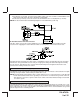
This Remote Start/Alarm System is designed to be used with Automatic Transmission- Fuel Injection Gas or Diesel Vehicles Only! INSTALLATION OF THE MAJOR COMPONENTS: CONTROL MODULE: PART # 1365030 Select a mounting location inside the passenger compartment (up behind the dashboard). The mounting location selected must be within 24" of the ignition switch wiring harness to allow connection of the 6 pin main wiring harness.
IMPORTANT! DO NOT PLUG THE SIX PIN MAIN POWER HARNESS OR THE MULTI PIN INPUT / OUTPUT HARNESS INTO THE CONTROL MODULE UNTIL ALL CONNECTIONS TO THE VEHICLE HAVE BEEN MADE. AFTER SELECTING YOUR TARGET WIRES AS DEFINED BELOW, DISCONNECT THE NEGATIVE BATTERY CABLE FROM THE VEHICLE BATTERY PRIOR TO MAKING ANY CONNECTIONS. NOTE: Do not remove the fuse holders from this wire harness. Fuses must be used and located as close as possible to the power source for adequate protection of the vehicle.
SEE NEUTRAL START SAFETY TEST FOR FURTHER DETAILS. YELLOW START WIRE DETAIL 6 GREEN Wire: Ignition 2 Output Connect this wire to the ignition 2 wire from the ignition switch. This wire will show + 12 volts when the ignition key is turned to the "ON" or "RUN" position and is some cases the "START" or CRANK" position. This wire will show 0 volts when the key is turned to the "OFF" and "ACCESSORY" positions.
WIRING CONNECTIONS: 18 Pin Accessory Input/Output Harness PART # 1123305 1 Black w/ White Trace Wire : 300 mA Horn Output The black w/ white trace wire is provided to beep the vehicle’s horn. This is a transistorized low current output, and should only be connected to the low current ground output from the vehicle’s horn switch.
4. Cut (#1) wire (as shown), and connect the ignition switch side of the cut wire to terminal #87a of the relay. Connect the other side of the (#1) wire to terminal #30. 5. Connect the previously selected resistor from terminal #87 to the second (#2) wire (as shown). NOTE: The above information and following diagram is for the GM VATS system only. D.
6 White w/ Black Trace Wire: (+) Siren Output This is the positive siren feed wire. Route this wire through a grommet in the firewall to the siren location. Connect the White w/ Black Trace wire to the Red wire of the Siren. Secure the Black wire of the Siren to a known chassis ground or solid clean metal surface. 7 Green w/ Orange Trace Wire: Tachometer Input Signal This wire will continually monitor the engine's tach rate while the unit is under power of the Remote Start module.
9 White Wire: Parking Light Flasher Output This wire is the normally open contact of the on board parking light flash relay. Connect this wire to the vehicle's parking light feed wire. This is the wire that gets switched on, either (+) or (-), when the vehicle's parking light switch is activated.
when the system is armed, the siren will emit three chirps. When the zone clears, the siren will emit 1 chirp to confirm full arming. NOTE: For vehicles with interior delay lighting see programming under title "Completing The Installation". 14 Purple Wire: (+) Door Trigger Input If the vehicle's door courtesy light switches + 12 volts when the door is opened, (some Fords and some imports), you must connect this wire to the positive output from one of the vehicle's door pin switches.
pin switch previously installed. This wire must be routed through a grommet in the firewall and connected to the hood pin switch. If connecting to a factory hood pin switch, it is recommended that a double diode circuit be used to prevent feed back of one device to the other. IMPORTANT! This connection is a safety wire and must be connected as shown and tested as specified. Failure to do so may result in personal injury or property damage. See the wiring detail in the following diagram.
2 Green: (+) Lock or (-) Unlock The Green wire provides a (+) Positive Pulse when locking and a (-) Negative Pulse when unlocking. 3 Red/Black: (-) Second Unlock The Red w/Black trace wire will provide a pulsed ground only, and will only provide an output when the unlock button of the transmitter is pressed a second time after a first unlock command was issued. This is used for second step unlock or all doors unlock in a two step circuit.
3 Wire Positive Switched Door Locks: In this application, the Red wire of the door lock harness provides a + 12 volt pulse during the disarming sequence, or pulsed 12 volt unlock output. Connect the Red wire to the low current 12 volt signal wire from the factory door unlock switch to the factory door unlock relay. The Green wire of the door lock harness provides a + 12 volt pulse during the arming sequence, or pulsed 12 volt lock output.
WIRING THE 4 PIN AUXILIARY OUTPUT HARNESS Part #1122585 The auxiliary 4 pin connector provides low current outputs to control various functions in the vehicle during different stages of the Remote Start unit's operation. Understanding these outputs and the time in which they occur will allow you to determine if they are needed for the particular vehicle you are working on as well as how to use them.
1 Black: 250mA Output (-) The black wire switches on when the remote start is activated and will stay on as programmed in the remote start feature Bank3 Feature 12. 2 Red: 250mA Output (+) 12 Volts Constant This output is intended to allow the control of a transponder bypass interface module or transponder bypass relay.
and fluids warm. The operator has the option to have the unit start every 2 or 4 hours for a maximum of 48 hours. Factory preset is to start at 4 hour intervals. To select 2 or 4 hour automatic start timer: 1. Start By Holding the Push Button Switch found on the windshield mount receiver on. 2. While Holding the Push Button Switch Turn The Ignition Switch On Then Off 3a.
3) DBI TACH SETTING Selecting this setting in the option menu indicates that you have a DBI module and have determined that a tach signal is available for the vehicle you are connecting to. The unit will look at the DBI data port for the tach signal. If the vehicle fails to start, or the unit flashes 7 times, recheck the DBI manual to insure that tach is available for your vehicle. If not the tach connection wire, Green/Orange must be used.
TESTING YOUR INSTALLATION: WARNING!! The following procedure must be performed after the installation of any Remote Start Device. It is the responsibility of the installing technician to complete these tests. Failure to test the unit in the following manner may result in personal injury, property damage, or both.
To Exit Remote Start Override Mode: 1. With the system disarmed, Press and Hold the PBLED on. 2. Turn the ignition switch on, off, on, off, on, off. 3. The LED turns off indicating that the R/S unit is fully functional one again. DO NOT RELEASE THIS VEHICLE TO THE CONSUMER UNTIL YOU CONFIRM THE OPERATION OF THE MANUAL SHUT DOWN / ENABLE FEATURE.
CAUTION! REMEMBER TO RECONNECT THE BROWN/BLACK NEUTRAL SAFETY WIRE TEMPORARILY DISCONNECTED IN STEP 3 MECHANICAL NEUTRAL SAFETY SWITCH CONSIDERATIONS: Mechanical neutral safety switch configurations differ slightly in that they do not offer the same level of safety when installing a remote start device.
METHOD 1 To connect to the key in sensor as shown in method 1: 1. Locate the control wire that connects the drivers door pin switch to the key in sensor switch. 2. Cut this wire and connect the ignition cylinder side to chassis ground. 3. Locate the key in sensor switch wire that connects the chime module to the ignition cylinder . 4. Cut this wire and connect the ignition cylinder side to terminal 30 of a P&B VF45F11 or equivalent relay. 5.
METHOD 2 To connect to the key in sensor circuit as shown for method 2: 1. Locate the control wire that connects the drivers door pin switch to the key in sensor switch. 2. Cut this wire and connect the ignition cylinder side to chassis ground. 3. Locate the key in sensor switch wire that connects the chime module to the ignition cylinder . 4. Cut this wire and connect the ignition cylinder side to the Remote Start Negative Safety Shut down Wire Gray/Black, using a 4002 series diode as shown above.
DOME DELAY LEARN FEATURE: This unit has the ability to learn the dome light delay time, up to 60 seconds. If the vehicle has delay interior lights, and you wish to avoid three chirp, defect zone, indication normally associated with this type of interior light, we suggest you learn the interior light delay. To learn the light delay, start with all doors closed: 1. Use the transmitter to Lock / Unlock / Lock / Unlock / Lock / Unlock / Lock, the system.
COMPLETING THE INSTALLATION: After you have confirmed the operation of the Remote Start unit and tested all the safety features of the system: 1. Mount the control module up and behind the dash securing it in place with cable ties or screws. Be certain that the chosen mounting location will not inhibit any of the controls of the vehicle. 2. Securely harness and tie all wiring up and away from all hot and moving parts that they may come in contact with under the dash board or in the engine compartment areas.
INSTALLATION NOTES 27 128-8787b 27 of 32
The transmitters are pre-programmed from the factory, If you find you need to program new or additional transmitters follow the instructions below. PROGRAMMING BANK 1 (TRANSMITTERS): 1. Turn the ignition key to the on position. 2. Press and release the valet/programming switch 3 times (Siren Chirps). 3. Press the Lock Button of each transmitter you want programmed until you hear a chirp from the horn or siren. 4. Turn the ignition switch off.
128-8787b 29 of 32 1 Chirp 1 Sec. Auto Lock On Auto UL Dr. Not Available Passive Passive Arm Siren/Horn 10mS Custom Code On On Not Available All On Not Available Pulse Pulse Pulse Not Available Hood/Trunk Off 10 Sec 10 Sec 10 Sec Push & Hold Push & Hold Push & Hold Horn Only 30mS Auto UL Off 3 Chirps 1 Sec L, Dbl. U/L Doors Off Active Active Arm Siren Only 16mS Valet Off Off 2 Chirps 3.5 Sec. Auto Lock Off Auto UL All 5. Siren chirps 2 times indicating access to RF feature program mode. 4.
PROGRAMMING BANK 3 (REMOTE START ): You can enter Bank 3 from Bank 2 by turning the ignition key off then on after you've made the changes you wanted in Bank 2, (Siren two Long Chirp). You can also go right to bank 3 by: 1. Turn the ignition key to the on position. 2. Press and release the valet/programming switch 3 times (Siren Chirps). 3. Turn the ignition key off then on. (Siren Short Then long Chirp) 4. Turn the ignition key off then on. (Siren two Long Chirp) 5.
128-8787b 31 of 32 0.8 Sec Gas While R/S On Not Available Averaging 10th Crank Time 11th Gas/Diesel 12th Transponder O/P 13th Temp Start 14th Crank Averaging Preset Time During Start Diesel 10 1.0 Sec On One Press 45 Mins 5 Chirps 5 Mins 10 Mins 4 times with the key to be effective. Shunt From Tx 60 Mins 6 Chirps 5. Siren chirps 2 times indicating access to RF feature program mode. 4. Press and hold valet switch for 5 seconds. 3. Turn ignition off then on. not start.
For technical support go to www.pursuitcarsecurity.com or call 1 800 225 6074. © 2013 Audiovox Electronics Corp., Hauppauge, N.Y.