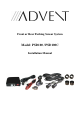
Front or Rear Parking Sensor System Model: PSD100 / PSD100C Installation Manual
TABLE OF CONTENTS Warnings.......................................................................................4 Product Description ......................................................................5 Packing List ..................................................................................6 Installation Instructions ................................................................7 Mounting the Sensors .......................................................7 Installing the Power Harness (REAR)...
Features • • • • • • • • • • • Front or rear install Adjustable range to 7ft Adjustable sensitivity Upgradeable to a 4-sensor system (requires part #: PSD200/PSD200C) Learning capability to ignore vehicle mounted objects Auto-mute capability for use with trailer Easy install active learning front system Includes 0° and 8° sensor sleeves to fit most bumpers Will not drain battery or void factory warranty Includes adjustable speaker with tricolor LED Works with any vehicle 2
Warnings This product is intended to assist in safe driving by signaling the driver of the distance to obstacles in close proximity to the vehicle while the vehicle is in reverse or moving forward slowly. You, as the driver, are solely responsible for the safe operation of your vehicle and the safety of your passengers according to your local traffic regulations. Do not use any features of this system to the extent it distracts you from safe driving.
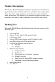
Product Description This Front or Rear Parking Sensor System is designed to assist the driver by providing an alert when the vehicle is traveling toward a nearby object. Never rely solely on this product to ensure the area is clear of children and/or obstructions. This product is not intended to replace existing safety procedures, but rather to add an additional safety tool for your vehicle. Packing List The model PSD100 Front or Rear Parking Sensor System consists of the following items: 1. 2. 3. 4. 5. 6.
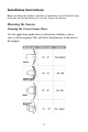
Installation Instructions Before installing this product, take time to familiarize yourself with the items in the box and use the packing list to verify all parts are present. Mounting the Sensors Choosing the Correct Sensor Sleeve Use the application guide below to determine whether a sensor sleeve will be required. This will affect the diameter of the hole in the bumper.
Marking and Drilling Holes Figure 1 (2 sensors) Figure 2 (4 Sensors) 1. Mark the locations of the sensors on the front or rear bumper using a grease pencil. a. Identify the sensors height on the bumper and mark. The sensor height should be between 18” and 30” from the ground. b. Divide the bumper as shown in Figure 1 for a two sensor install, or as shown in Figure 2 for a four sensor install. c. Install the sensors equally from the center of the bumper as shown in Figure 1 and Figure 2. d.
Installing the Sensor Sleeve and Sensors NOTE: When installing the sensors into the sensor sleeves, push on the outer ring of the sensor only. Never push on the center of the sensor. 1. Ensure sensors and sleeves are upright (all products have an alignment mark on the top). 2. If required, install the sensor into the sleeve. 3. Install the sensor (with sleeve, if required) into the holes drilled in the bumper. 4. Run the sensor wires through the sensor sleeves in the bumper. 5.
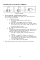
Installing the Power Harness (REAR) Tap/Run Connection 1. 2. REAR SENSORS - POWER HARNESS INSTALL. For installation in the REAR of the vehicle, locate a source of reverse power (usually at taillight assembly) and accessory power (usually cigarette lighter). a) REVERSE POWER Using the tap connector supplied, perform the following steps: i. Place the un-stripped positive reverse power lead wire on the run channel. ii. Insert the un-stripped RED power wire completely. iii.
Installing the Power Harness (FRONT) Tap/Run Connection 1. 2. FRONT SENSORS - POWER HARNESS INSTALL. For installation in the FRONT of the vehicle, locate a source of accessory power (usually cigarette lighter). a) ACCESSORY POWER i. Place the un-stripped accessory lead wire on the run channel. ii. Insert the un-stripped RED ground wire completely. iii.
Mounting the Speaker The speaker has three volume settings: Off, Hi, and Low. Since the speaker can be adjusted as needed, you should mount the speaker in an accessible location in the interior. It is recommended that the speaker for the Rear detection system is mounted behind the driver and that the Front detection system is mounted in front of the driver. 1. Route the wires for the speaker to the area where you will install the control module.
Mounting the Mute/On-Off Button The PSD100 system has an optional mute/on-off switch. When installed with a rear system, the button will mute the rear PSD system until the ignition is turned off and back on. When installed on a front sensor system, the button serves as an on/off switch for front detection. To install the Mute/On-Off button: 1. Determine a suitable place to mount the button. 2. Route the wires for the button to the area where you will install the control module.
Mounting the Control Module Determine a dry place inside the vehicle (out of the way) to mount the control module (e.g., behind an inner body panel), making sure that all wiring will reach the intended location. 1. Plug the sensor wires, speaker and power harness into the control module before mounting. The sensor must be plugged into the corresponding socket (see Figure 4). The control module is pre-fitted with Velcro for mounting. 2. Clean the pre-selected mounting area to ensure good adhesion. 3.
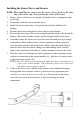
Setting the Learning System (Rear Sensors) If an object mounted on the vehicle is causing the Rear sensor system to false alarm (tow bar, rear mounted tire, bicycle rack etc.) you can ‘train’ the PSD system to ignore these obstacles. 1. Place the vehicle in an area at least 15ft away from obstacles. 2. Start the engine and leave it running. 3. Place the vehicle in and out of reverse gear 4 times at 1-2 second intervals, ending with the vehicle in reverse.
Specifications Power Supply Current Draw Detecting Distance Sensor Cable Length Operating Temperature Range DC9V-DC16V <120mA 0ft – 7ft 19.68ft -0°F ~ 176°F Maintenance Though your backup system requires minimum care, you should maintain its condition and performance using the following the guidelines: • Keep the control box away from moisture, extreme heat or cold. • Keep the sensors free from snow, ice, and debris. Diagnostics / Trouble Shooting Problem No sound when reverse gear is engaged.
15
© 2008 Audiovox Electronics Corp., 150 Marcus Blvd.