
Technical data
Instructions for Use
3339135: 16th Edition : November 2009 : Subject to Modication - (A3-D-P)
AirBoss
TM
EvoluTion, AirBoss
TM
EvoluTion Plus And ProAir
TM
EvoluTion
CoMPrEssEd Air rEsPirATory ProTECTion EquiPMEnT
1
Approvals
AirBoss
TM
Evolution, AirBoss
TM
Evolution Plus and ProAir
TM
Evolution are positive pressure,
open circuit, self contained compressed air respiratory equipment certied by NIOSH/MSHA.
AirBoss
TM
Evolution, AirBoss
TM
Evolution Plus and ProAir
TM
Evolution must only be used in
conjunction with compressed air cylinders approved by NIOSH/MSHA.
For Your Safety
AirBoss
TM
Evolution, AirBoss
TM
Evolution Plus and ProAir
TM
Evolution approved equipment
incorporates Dräger pre-set, and sealed pressure reducer and balanced piston unit assemblies. Drägers’
guarantee is void should original seal caps be tampered with, removed, or broken. Correct operational
condition is only valid if Dräger service, and re-seals pressure reducer and balanced piston unit.
Use of this equipment requires wearer training, knowledge, observance of these User’s
Instructions, and compliance with National Regulations, Laws and Standards, governing the
use of respiratory equipment in the country of use.
Use equipment only for the purpose specied in this manual, or as conrmed in writing by Dräger.
Guidelines for proper use of equipment should be consistent with NFPA 1500 - standard on
Fire Department Occupational Safety and Health Program.
Trained personnel should inspect and service equipment at regular intervals and a record kept
of such inspections and servicing.
Dräger recommends a service contract be obtained from your Dräger Branch or Agent.
Contact Dräger for details of Service Contracts and Service Training Courses.
Use only original Dräger Spare Parts for service and maintenance.
Notify Dräger in the event of component fault or failure.
Use only Dräger Test Equipment for service and maintenance.
Warranty and Liability Statement
Terms and Conditions of warranty, for the AirBoss
TM
Evolution, AirBoss
TM
Evolution Plus and
ProAir
TM
Evolution, can be obtained from Dräger on request.
Responsibility for reliable function of equipment transfers to the owner or operator when serviced,
or repaired by untrained personnel, (not employed or authorised by Dräger) or when used in a
manner not conforming to its intended use.
Description
Researched and designed to meet the
specic needs of the end user, the AirBoss
TM
Evolution, AirBoss
TM
Evolution Plus and
ProAir
TM
Evolution variants utilise the same
high performance rst stage pressure reducer,
lung demand valve, carbon composite backplate
and are fully compatible with a wide range of
compressed air cylinders and facepieces.
The above variants can be tted with either a
Mechanical Gauge, Flashing Gauge or Sentinel.
Details of equipment variants and approved
accessories are available from Dräger on request.
Intended Use
AirBoss
TM
Evolution, AirBoss
TM
Evolution
Plus and ProAir
TM
Evolution positive pressure
two stage compressed air respiratory protection
equipment, used in approved cylinder, facepiece
and demand valve combinations, provide the
wearer with respiratory protection when working
in a contaminated, or oxygen decient gaseous
atmosphere.
Eective working duration of equipment is
dependant on capacity (volume) of cylinder
selected and breathing rate of wearer.
Technical Data
High Pressure Connection
2216 psi connection to CGA 346
4500 psi connection to CGA 347
Lung Demand Valve to Facepiece
Connection
Push-In - Positive Pressure with By-pass
Pressure and Flow - Equipment
Medium Pressure: 87 psi to 130 psig
Air Flow: in excess of 1000 litres/minute.
at 290 psig in excess of 500 litres/minute.
Pressure and Flow - Airline Supply
If equipment tted to independent air supply,
the following parameters should be noted:
Air Supply Pressure: 90psig to 120psig
Airline Hose Length: 5 feet to 300 feet
Note: maximum working length of hose Must
Not be made up of more than 12 individual
hose lengths.
Safety Note: Air quality Must conform to
the minimum grade requirements for Type 1
Gaseous air as dened in Compressed Gas
Association Commodity Specication for
Air, G-71 (Grade D or higher quality). Use
of airline connection by a second person,
Buddy Breather, voids NIOSH approval.
Whistle Setting (Flashing Gauge)
Whistle setting for the following pressure units
is as follows:
2216 psi Unit - setting 510 psig to 600
psig
4500 psi Unit - setting 1035 psig to 1215
psig
The activation setting of the LED’s of the
Flashing Gauge (if tted) is also within the
above setting parameters.
Weights
AirBoss
TM
Evolution, AirBoss
TM
Evolution
Plus and ProAir
TM
Evolution Self Contained
Breathing Equipment (without cylinder) -
8.5lbs.
Charged Compressed Air Cylinders
4500psi/60 minutes (Carbon composite) 19.0lbs
4500psi/60 minutes (Kevlar composite) 22.0lbs
4500psi/60 minutes
(Fibreglass composite) 26.5lbs
4500psi/45 minutes (Carbon composite)
14.8lbs
4500psi/45 minutes (Kevlar composite)
17.0lbs
4500psi/45 minutes
(Fibreglass composite) 20.6lbs
4500psi/30 minutes (Carbon composite) 11.4lbs
4500psi/30 minutes (Kevlar composite) 12.4lbs
4500psi/30 minutes
(Fibreglass composite) 13.2lbs
2216psi/30 minutes (Carbon composite)
12.0lbs
2216psi/30 minutes
(Fibreglass composite) 13.9lbs
2216psi/30 minutes
(Hoop Wrap, Fibreglass) 16.3lbs
2216psi/30 minutes (Full Aluminium) 21.4lbs
Equipment Dimensions
Data indicated is less cylinder and with carrying
harness folded in stowage condition.
Length: approx. 24.5 inches
Width: approx. 12.5 inches
Height: approx. 6 inches
Preparation for use
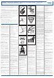
Flashing Gauge - Fitting Batteries
If Flashing Gauge tted – t new batteries
as follows:
Fold back rubber cover from the gauge to
access the battery cover.
Refer to Fig. 1. Using TORX
TM
- TX 8
unscrew the four captive screws and carefully
remove the battery cover taking care not to
damage the sealing gasket.
Insert two new batteries into the battery
compartment ensuring correct positioning of
terminals.
Check that sealing gasket is not damaged.
Relocate battery cover and secure using the
four captive screws. Do Not overtighten
(max. 0.4Nm).
Reposition rubber cover over the gauge.
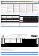
Fitting Cylinder
Check valve port and the reducer handwheel
threads are undamaged, connector O ring
is in position, and undamaged.
Place the backplate horizontal, extend
the cylinder strap, slide cylinder through
strap locating the valve port to the reducer
handwheel.
Lift unit upright, screw the handwheel into the
valve port, (handtight). Do Not use tools.
Place backplate horizontal, take up slack on
cylinder strap (Fig. 2) pull strap over cylinder
to activate Camlock (Fig. 3) secure strap to
Velcro.
Pre Operational Checks
High Pressure Leak Test
Press reset (1 Fig. 9) mechanism of the lung
demand valve to switch ‘O’ positive pressure.
Open the cylinder valve slowly, but fully, to
pressurise system.
Note: If an immediate leak is indicated from
the demand valve - press the centre of the
rubber cover to release the positive pressure
mechanism - press reset mechanism to
switch ‘O’ positive pressure. Repeat the
action two or three times to eliminate the
leak. If leak not eliminated return balanced
piston unit to Dräger Service.
Close the cylinder valve and observe the
pressure gauge.
Gauge reading shall not decrease more than
200psig in 1 minute.
Whistle Warning Unit Test
Cover the outlet of the demand with ball of the
hand, press the centre of the rubber cover,
turning ‘On’ positive pressure. Slowly vent
system by carefully lifting the ball of the hand
maintaining a slow decrease in pressure.
Observe the gauge. Whistle should sound
at the preset pressure.
Note: Whistle pre-set by Dräger to the
following values:
2216 psi Unit - 510psig to 600psig
4500 psi Unit - 1035psig to 1215psig
Should whistle not sound at the required
pressure, refer to Service Manual.
Important Note: The activation setting of the
LED’s of the Flashing Gauge (if tted) is also
within the above setting parameters. Audible
and visual signals/warnings may however
not activate at exactly the same time. The
LED’s of the Flashing Gauge will switch o
before the audible warning at the following
approximate values,
2216 psi Unit – below 200psig
4500 psi Unit - below 400psig
Following satisfactory whistle test, press reset
mechanism to switch ‘O’ positive pressure.
Connecting Demand Valve to
Facepiece
Check that the facepiece port and the demand
valve O ring are clean and undamaged.
Push the demand valve into the facepiece
port until it clicks into position. A slight turning
motion of the LDV during pushing will aid
connection.
Check that the attachment is secure. Pull
the demand valve away from facepiece - there
should be no axial movement.
Operation
Putting on equipment
Extend the waistbelt and shoulder adjusting
straps.
Put on equipment taking weight on
shoulders by pulling on shoulder adjusting
straps. Do Not tighten.
Fasten waistbelt buckle. Pull ends of waistbelt
adjusting straps (see Fig. 4) until waistbelt pad
is secure and comfortable on hip. Tuck strap
ends between body and waistbelt pad.
Pull down shoulder adjusting straps (Fig. 5)
until equipment is secure and comfortable.
Do Not overtighten. Tuck strap ends under
waistbelt.
Extend facepiece head harness straps, leaving
centre strap in position, (Fig. 7). Put neck
strap over neck, insert neck strap stud into
hole in centre strap of head harness.
Carry out High Pressure Leak Test.
Note: Cylinder pressure must not be less
than 80% full. If pressure is below maximum
charging pressure of the cylinder, this will
reduce available duration to the wearer.
Press the reset mechanism of the demand
valve to switch ‘O’ the positive pressure.
Open the cylinder valve slowly, but fully, to
pressurise the system. Check the gauge.
Putting on Facepiece
Safety Warning: Beards, side whiskers,
facial stubble and/or spectacle frames will
interfere with face seal of facepiece, and
adversely aect protection of the wearer.
Detach the neck strap stud from the centre
strap of the head harness.
Spread the harness, (Fig. 7) then place chin
into the facepiece, position harness over the
head locating the harness centre plate with
the back of the head.
Tighten both the lower, then the upper straps
evenly towards back of the head. Fig. 8. Tuck
in strap ends.
On achieving a face seal the positive pressure
demand valves will automatically activate on
rst breath inhalation.
Breathe normally then prior to use perform
function checks.
Function Checks
Inhale and hold breath. Unit must balance,
i.e. no audible leak.
Continue breathing. Expired air should easily
ow out of the exhalation valve.
Press the ‘red’ by-pass button of the demand
valve checking that an additional airow is
delivered into the facepiece.
Close the cylinder valve. Breathe normally to
vent the system. When the gauge indicates
zero, hold breath. Facepiece should hold
onto the face indicating a positive seal.
Note: If a leak detected, open the cylinder
valve, readjust the head harness and retest.
Open the cylinder valve slowly, but fully to
pressurise the system, recheck the pressure
gauge and proceed.
Use
Take gauge reading regularly. Whistle will
sound at whistle warning unit pressure
setting.
Proceed to safe area, at least when whistle
sounds, by shortest and safest route.
Important Note: The activation setting of the
LED’s of the Flashing Gauge (if tted) is also
within the whistle setting parameters. Audible
and visual signals/warnings may however not
activate at exactly the same time. The LED’s of
the Flashing Gauge will switch o before the
audible warning.
Safety Notes:
a. Additional Air Required
If momentary additional airow is required, press
‘red’ bypass button of lung demand valve. In the
unlikely condition of low or blocked airow, or
if required to maintain additional airow, press
and rotate the ‘red’ bypass button to ‘lock’ the
ow setting (80 - 130Litres/min). Duration of
the air supply is reduced while the bypass is
in operation. When set in this condition the
wearer must evacuate to a safe area. If it is
suspected that the apparatus is blocked then an
investigation by a trained authorised person must
be carried out before re-using the apparatus.
b. Excessive or Loss of Airow
In the unlikely condition of high or loss of
airow, close the cylinder valve then immediately
begin to slowly re-open the valve, using it as
an adjusting valve to set sucient airow to
cover the maximum inhalation requirement.
This action must only be carried out in an
emergency situation to escape to a safe area. An
investigation by a trained authorised person must
be carried out before re-using the apparatus.
Note: On SCBA having cylinders tted with
a locking (ratchet) valve, adjustment of the
cylinder valve while wearing the SCBA must
be performed as follows. Reach behind with
the left hand to support the backplate and
at the same time with the right hand, push
and hold in the valve handwheel, rotating the
handwheel clockwise to close the valve then
immediately begin to slowly re-open the valve,
using it as an adjustment valve to set sucient
airflow to cover the maximum inhalation
requirement. Release the valve handwheel
when the required airow is achieved.
Connecting to Independent Air Supply
Note: Ensure independent air supply source
meets pressure and air quality requirements
as dened in Technical Data section of this
User’s Instruction.
Turn ‘On’ the independent air supply then
connect air supply hose to the coupling of
the Buddy Breather connection.
Close equipment cylinder valve and breathe
normally from the independent air supply.
IN AN EMERGENCY - If independent air
supply ‘Fails’, proceed as follows:
Open cylinder valve slowly but fully. Breathe
normally.
Disconnect air supply hose from Buddy
Breather connection.
If necessary leave hazardous area by
shortest and safest escape route.
After Use
Safety Warning: Do Not remove equipment
until in safe area, clear of hazard.
Release the side straps of the head harness,
press the reset mechanism of the demand
valve to switch ‘O’ the positive pressure
then remove the facepiece.
Close the cylinder valve.
Unbuckle the waistbelt, lift shoulder strap
buckles to loosen, remove the equipment.
Note: Do Not drop or throw down equipment
as damage could occur.
Press centre of the rubber cover of the demand
valve to vent system. Following venting press
the reset mechanism of the demand valve to
switch ‘O’ positive pressure.
Note: If the by-pass has been set in constant
ow position, turn the ‘red’ button to unlock,
and switch ‘O’ the by-pass.
Pass equipment to the Service Department.
Routine Maintenance
To be performed after Use.
See also Maintenance and Test Intervals Chart.
Removal of cylinder
Safety Warning: Cylinder valve should be
closed and system vented.
Lift free end of the cylinder strap against the
Camlock to release, loosen the strap. Unscrew
handwheel from cylinder valve. Slide cylinder
away from reducer, remove from equipment.
Recharge the cylinder.
Charging Cylinders
Safety Warning: Air quality for compressed
air cylinders must conform to the minimum
grade requirements for Type 1 gaseous
air as defined in the Compressed Gas
Association Commodity Specication for
Air, G-7.1 (Grade D or higher quality).
To prevent ingress of moisture into the cylinder,
ensure that the cylinder valve remains ‘closed’ until
connected to the charging unit.
Dräger recommends that the moisture content in
charged cylinder should not exceed the following:
2216 psig Units
50 mg/cubic meter (4.99 x 10⁻⁵ ounce/
cubic feet.
4500 psig Units
35 mg/cubic meter (3.49 x 10⁻⁵ ounce/
cubic feet.
Safety Warning: If moisture content exceeds
recommended levels, ice particles can
form reducing, or blocking air ow. Water
content of breathing air must be checked.
Recharge to the indicated pressure stamped on
the neck, or shoulder of the cylinder.
Visual Inspection
Check integrity of:
Carrying plate.
All straps, buckles and harness.
Valves, connectors and cylinder supports.
Facepiece.
Flashing Gauge – if tted
Replace batteries annually regardless, or when the
brilliance of the LED’s is signicantly reduced.
Note: Use only approved batteries. Refer to
the specications detailed on the label of the
gauge battery cover.
Cleaning, Disinfecting, Drying
Carefully clean, disinfect, and thoroughly dry
contaminated dirty components as necessary.
Use suitable baths for containing cleaning and
disinfecting solutions. Immerse and manually
agitate components in solutions. Dräger
recommends that no form of mechanical,
electrical or ultrasonic agitation be used.
Safety Note: Refer to manufacturers’ usage
instructions when using cleaning and
disinfecting agents. It is important that
attention be paid to concentration and
reaction times. Do Not use organic solvents,
such as Acetone, Alcohol, White Spirit,
Trichloroethylene or similar.
Dräger recommends the following:
Cleaning
Dräger Safety Wash.
Do Not exceed a temperature of 86
degrees Fahrenheit.
Disinfecting
Incidur.
Do Not exceed a temperature of 86
degrees Fahrenheit.
Details of cleaning and disinfecting agents are
available from Dräger on request.
Rinsing and Drying
Remove cleaning and disinfecting solutions by
rinsing in clean water, followed by drying.
Do Not exceed a temperature of 140 degrees
Fahrenheit when drying components.
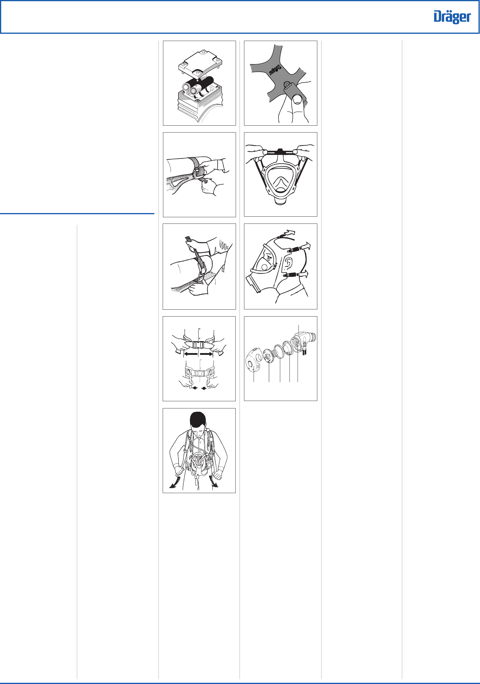
Lung Demand Valves
It is important to follow these instructions to
internally clean and disinfect the lung demand
valve.
Refer to Fig. 9.
Fold the rubber cover (2) from the front of
the demand valve body. Grip the bayonet
cap (3), turn anticlockwise and remove the
bayonet cap.
Note: The positive pressure spring remains
attached to the bayonet cap. Do Not remove,
stretch or compress the spring. Take care not
to damage the spring during cleaning and
disinfecting procedures.
Using the thumb and forenger carefully grip
centre plate of the diaphragm (4) then tilt the
centre plate and lift the diaphragm from the
body of the demand valve. Remove the slip
ring (5).
Note: The diaphragm must not be ultrasonically
cleaned as this will aect the bonded area of the
diaphragm. Clean and disinfect manually.
Fold rubber cover back over the front of the
demand valve body to protect the lever (6)
of the balanced piston.
Immerse, and manually agitate the demand
valve, diaphragm, slip ring, and bayonet cap
in cleaning uid. (Refer to cleaning uid
instructions.)
After cleaning, rinse components in clean
water.
Immerse and manually agitate components in
disinfecting uid. (Refer to disinfecting uid
instructions.)
After disinfection fold the rubber cover from the
front of the demand valve and rinse components
in clean water. Take care not to damage the lever
(6) of the balanced piston.
Connect the hose of the demand valve to a
medium pressure air supply. Press reset (1)
then turn ‘ON’ the air supply.
Gently press lever (6) blowing out fluid
residue.
Safety Note: Wear suitable eye protection.
Disconnect from air supply, dry the components
and, if necessary remove the excess uid.
After drying, carefully locate the outer bead
of diaphragm into groove in the demand
valve body.
8
1
2
3
0018
0016
6
0017
7
0584
6
4
53
9
2
1
3
0157
0156
2
1146
4
ProAir
TM
Evolution
AirBoss
TM
Evolution
0020a/0163
5
0153
1