Audiovox® Skybox Installation & User Manual Disclaimers This manual is in draft form and is intended for the purpose of review or to validate the method of installation.The beta tester receiving the Audiovox® Skybox beta antenna agrees to utilize the Draft Manual for the purpose of validating its content only, and agrees to validate and provide feedback to Audiovox®, Inc., in appropriate commercial settings. This manual is subject to revision without notice.
Contents Skybox Installation & User Manual.................................................................................................1 Disclaimers....................................................................................................................................... 1 1 Welcome........................................................................................................................................4 1.1 Installation & User Guide..............................................
Contents 7.2 Setting Up the Remote Control...............................................................................................23 7.3 Audio/Video Cable Connections.............................................................................................23 7.3.1 RCA A/V Connection.............................................................................................................23 7.3.2 S-Video Connection...................................................................................
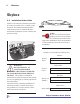
1 Welcome Skybox 1.1 Installation & User Guide Skybox is the innovative antenna system that provides live satellite TV to a vehicle, while in motion. This manual will provide basic instructions on how to install the Skybox antenna and components in most vehicles and operate it safely. DO NOT VIEW� from� Drivers Seat NOTE Be sure to record serial and part numbers of the receiver, antenna and indoor unit, in the boxes provided on this page before installation.
1 1.2 Welcome Icons User-friendly icons provide a visual reminder to mark the important information necessary to successfully operate and install the Skybox antenna system. They include: WARNING Alerts installers and customers of important information regarding personal safety to avoid bodily injury. CAUTION Alerts installers and customers to possible electrocution hazards. TOOLS & REPAIR Marks the areas requiring special tools and installation procedures.
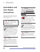
2 Safety Instructions Installation and User Safety Instructions Read this manual thoroughly and carefully before attempting to install or operate any Skybox antenna system. Observe Warnings - Be sure to follow all warnings and cautionary instructions in this manual. Follow Instructions Observing these instructions is critical to ensure proper installation. Follow each detail to ensure accurate and safe installation.
WARNING Do not open or remove the cover of the receiver, antenna or indoor unit (IDU) to avoid exposure to dangerous voltage. CAUTION The Skybox antenna system is specifically designed for use as it comes shipped – with the housings and unit covers intact. Any attempt to modify or to retrofit this product or its components will void the warranty and may be hazardous. WARNING To avoid fire or electrical shock by the receiver or other components, do not expose them to rain or moisture.
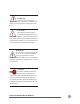
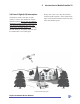
3 Receiving Mobile Satellite TV 3.1 Signal Reception The Skybox antenna can be used to receive satellite television via the direct broadcast service (DBS) satellites, located 22,000 miles in space. This system requires a clear view of these satellites to maximize the signal reception. Other factors, such as satellite coverage area, elevation angle, and weather also contribute to the signal quality (Figure 3-1). Introduction to Mobile Satellite TV 3.
3 3.4 Line of Sight (LOS) Interruption The Skybox needs a clear line of sight (LOS), or view to the satellite for uninterrupted reception. Objects such as buildings, mountains, bridges, tunnels, overhead road signs and trees that block this view will cause a loss of signal (Figure 3-2). The signal will, however, be quickly restored once the antenna has a clear LOS again. Introduction to Mobile Satellite TV Heavy rain, snow or ice may also interfere with the signal reception.
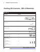
4 Satellite TV System Overview Packing Kit Contents - Bill of Materials Box No. 1 Description Quantity Skybox 1ox11 Allen Wrench 1 No.
4 Satellite TV System Overview Di re ct TV Di re cT V\ Ec ° ho Di st re ar cT V\ 14 Ec 8° ho Ec st ho ar st ar STANDBY ° SELECT 11 9 NI MI Q1 10 1° 11 0 NI MI Q2 ° 1 91 ° Indoor Unit 61 .5 ° Quantity 82 Description Ec ho st ar Box No. 2 ON/OFF User manual 1 Installation manual Connector, coaxial, TNC plug crimp 1 RF Cable , ODU to IDU 1 IDU End DC power supply cable ODU End 1 Remote extender TX 1 adaptor with batteries Box No.
4 Satellite TV System Overview 4.1 System Components The Skybox satellite TV delivery system requires the following components: 4.1.1 Antenna The Skybox antenna houses the antenna panels and electronics within a weathertight radome (plastic housing). It is mounted to the vehicle’s roof rack and connected with a single coaxial cable to the IDU inside the vehicle.
5 Mounting the Antenna to the Vehicle’s Roof Rack This section offers a general explanation of how to properly install the Skybox antenna to the vehicle’s roof rack. VERY IMPORTANT! Before operating the Skybox system, the end consumer shouldfill out the Audiovox® Customer Setup Form attached to this manual and fax to (703) 991-4556. This will save time when you go to activate the system. NOTE The Skybox antenna mounting hardware provided in your hardware kit will fit almost any design of roof rack.
Installing the Antenna 5 5.2 Clamp Design The Skybox antenna is designed to clamp onto a vehicle’s permanent roof rack with an adjustable, padded clamping system designed to secure the unit onto the fixed crossbars (Figure 5-2). Installers should confirm good condition of the roof rack and cross bars before installing the antenna. There are two different size bracket spacers provided in the kit: the 1 inch spacer comes installed between the bracket and antenna for ready-to-mount capability.
5 Installing the Antenna Figure 5-5 A 1-inch gap allows mounting space for antenna between the crossbars and roof rack. NOTE Use a towel or moving cloth to protect the roof of the vehicle while installing the antenna. CAUTION Failing to leave at least a 1 inch space between the Skybox antenna and the vehicle’s roof may result in damage to the roof and to the antenna due to the bouncing or movement of the antenna while the vehicle is in motion. 3.
5 Installing the Antenna 8. Select the proper bracket link size (approximately 1/2 inch, or 1-inch). Determine the link size based on the width of the crossbar (Figure 5-9). There are four combinations of bracket links and head screws that can be used. Choose the combination that will provided the best and most stable fit for your vehicle’s crossbar style. Figure 5-7 Centering the antenna on roof. 7.
5 Installing the Antenna CAUTION Make sure you are aware of the new maximum height of the vehicle (unloaded) with the antenna mounted onto the roof rack. Use caution when driving under overpasses, tree limbs, into garages and into low clearance areas. 10. Insert the bottom bracket into the bracket link (Figure 5-10). 11. Secure the bottom bracket with the appropriate head screw.
6 Installing the Antenna Cable Installing the Antenna Cable This section will explain the proper method for connecting the cable to the antenna, as well as routing the coaxial cable from the antenna to the Audiovox® indoor unit (IDU) location. NOTE Due to the extensive variety of vehicles on the market, it is impossible to cover all of the possible and appropriate wiring specifications for every vehicle.
6 2. Run the cable along the roof rack of the vehicle, back to the hatch. With the hatch open, route the cable behind the hatch to inside the vehicle (Figure 6-2 ). NOTE: Prior to the cable entering the vehicle, create a drip loop to prevent water entering the vehicle and causing damage. Installing the Antenna Cable 4. Once the cable has been routed from the antenna to the IDU, the cable must be properly secured to the roof rack crossbars with the supplied tie-wraps.
6 Installing the Antenna Cable NOTE Do not fold or kink the cable. Any bends should be gradual and kept to a 4-1/2 inch bend radius to avoid damaging the cable and degrading received satellite signals. 6.3 Technique 2 The second option for routing the cable from the antenna to the IDU, which may be used by trained installers, is to drill a small point of entry (POE) into the vehicle’s roof or body. Only a highly trained and qualified technician should perform this task.
7 Connecting the Skybox IDU and Receiver This section will explain the proper installation and connection of the Skybox indoor unit (IDU) and satellite receiver. NOTE Be sure to record serial numbers of the receiver, antenna and IDU, in the boxes provided on the front page of this manual before installation. These serial numbers will be needed to activate the receiver after installation. NOTE Do NOT remove the cover, obstruct or place anything into the ventilation slots of the IDU or satellite receiver.
7 Receiver Setup Figure 7-2 DISH Network Configuration.
7 7.2 Setting Up the Remote Control The remote control uses an IR signal to command the receiver. The IR signal must be converted to RF by attaching the remote control extender to the front of the remote. The IDU then receives the RF signal, converts it back to IR, and sends it to the receiver using the IR sensor cable. The 7ft IR sensor cable is attached to the IDU and has a small IR eye at the end. The IR eye must be adhered to the top of the satellite receiver (Figure 7-3).
7.3.3 RF Coaxial Connection 1. Connect one end of an RG6 RF cable to the RF Output of the satellite receiver. 2. Connect the other end of the RF cable to the RF or VHF/UHF Input of the vehicle’s entertainment system. NOTE RG-6 provides good picture quality, but is the least desirable for connection. For DVD or VCR connection, please refer to your satellite provider’s User Guide.
WARNING: DO NOT DISTURB ANY WIRES SHEATHED IN COLORED PLASTIC/PVC. THESE COULD BE AIRBAG CIRCUITS AND SHOULD NEVER BE DISTURBED! IF UNSURE, CALL TECH SUPPORT BEFORE CONTINUING. WARNING: Fuse the positive lead to protect the wiring and the vehicle at the source (12V Accessory) 6. With the key in the ‘start’ (do not turn engine over) carefully pierce the thickest wire with the red probe, making sure that you do not go through the wire into the next. Observe the DMM screen. If it reads ’12.
Functions of the Skybox Before powering on your Skybox, you should first understand some basic functionalities of this system. 8.1 Global Positioning System (GPS) When the Skybox is powered on, GPS is used to determine your physical location. This information is processed within the antenna and enables the system to acquire the satellite signal faster, usually within one minute. 8.2 Indoor Unit Select and Standby Buttons 8.
9 Operating the System DISH Network® Receiver Setup and Activation This section will explain the proper method for powering up the Skybox, as well as activation procedures for DISH Network®. NOTE: Before operating the Skybox, you must ensure that the vehicle is parked outside with a clear line of sight to the southern sky. VERY IMPORTANT! Before operating the Skybox system, the end consumer should fill out the Audiovox® Customer Setup Form attached to this manual and fax to (703) 991-4556.
9 Operating the System thus the vehicle ON. 11. About a minute later you should receive Message 061. (Figure 9-2) Figure 9-1 Point Dish Screen. 8. From the Point Dish menu, use the remote control to select satellite 119°. (Leave the transponder number that appears in the screen as is.) Once the antenna locks onto the satellite, the light indicator on the IDU will change to steady green. This means that your IDU has acquired the satellite signal. Verify that the signal strength is above 60.
9 Operating the System 17. You should receive Message 015. (Figure 9-4). 20. You will receive Message 058. (Figure 9-6) Please note and record these numbers. 1 4 Figure 9-6 Acquiring Satellite Screen. Figure 9-4 DISH Network activation screen. 21. After the Check Switch test has been completed, press the ‘Sys Info’ button again and look for “Section d.” You should see DP311M and Software ASD1. “Section h” should read MPD4X. 18. Within 1-2 minutes, the receiver will show Message 129.
25. You will see the following message on your monitor (Figure 9-8) Figure 9-8 Receiver Memory Screen. 26. Once activated, the Program Guide will be downloaded to your receiver. Upon completion, please confirm correct program selection for customer.
Appendix A Installing TNC Connector to RG58 Cable Procedures for Installing TNC Connector to RG58 Cable These procedures were written using Jye Bao Co. 8.7” Hex series crimp tool (CT-001) and TNC connectors (TNC3100-0058). 1. Strip the RG58 cable back 16.4mm from the end of the cable. Trim the braid back 8.2mm from the end. Strip the foam insulator back 4.7mm from the end of the cable. 4. Solder the center pin to the cable’s center conductor at the hole on the pin. 5. Fold the braid back from the cable.
Appendix B Troubleshooting Troubleshooting SKYBOX SYSTEM DOES NOT POWER ON: • Verify that the Indoor Unit (IDU) and receiver are powered on. • Check for blown fuses. • Remove and replace the power cord. • Verify vehicle battery has been reconnected properly. SKYBOX IDU DOES NOT LOCK ON SATELLITE: • Ensure that coaxial cable connections are installed properly. • Confirm clear line of sight to the satellite. • Check for green indicator above appropriate satellite on the IDU.
Appendix B Troubleshooting SKYBOX SYSTEM DOES NOT WORK IN MOTION: • Ensure that all cable connections are installed properly. • Confirm clear line of sight to the satellite. • Check for green indicator above appropriate satellite on the IDU. • Verify that the receiver is locked on the satellite from the Setup Menu of the receiver. CERTAIN CHANNELS DO NOT WORK OR ONLY PREVIEW CHANNELS ARE VISIBLE: • Verify channel package with satellite TV provider.
Apendix B Troubleshooting Indoor Unit does not lock on satellite X X X System continually resets X X X X X X Black or blue screen on TV X X X X Snowy television picture X X X X Intermittent picture for short intervals X X X X Picture jumbled, partial, or freezing X X X X System does not work in motion X X X X Certain channels do not work Place the IR transmiter according to the manual X Local channels are available in limited area check availability X Correct activ
12 MONTH LIMITED WARRANTY Applies to Audiovox Mobile Video Products AUDIOVOX ELECTRONICS CORP. (the Company) warrants to the original retail purchaser of this product that should this product or any part thereof, under normal use and conditions, be proven defective in material or workmanship within 12 months from the date of original purchase, such defect(s) will be repaired or replaced with reconditioned product (at the Company's option) without charge for parts and repair labor.