General Mobile Radio Service (GMRS) Model : GMRS6000-2PK Bonus Pack Owner’s Manual HI LO MODE VOX S Customer Service 1-800-290-6650 Released: 2-10-04 128-7029 1 of 28
THIS PAGE LEFT BLANK INTENTIONALLY 2 128-7029 2 of 28
CAUTION SAFETY INFORMATION Your wireless hand-held portable transceiver contains a low power transmitter. When the PTT button is pushed (or the VOX mode is enabled) it sends out radio frequency (RF) signals. The device is authorized to operate at a duty factor not to exceed 50%. In August 1996, the Federal Communications Commissions (FCC) adopted RF exposure guidelines with safety levels for hand-held wireless devices.
WARNINGS: Battery Care Never attempt to charge alkaline or dry cell batteries, as batteries may burst causing personal injury and damage to the product. If rechargeable batteries are used, such as Nickel Metal Hydride (NiMH), use only the supplied Audiovox-approved rechargeable batteries. Use of the Audiovox charger (also supplied) with other brands of batteries is not recommended, as battery charging times will vary with different brands.
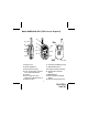
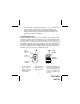
Model GMRS6000-2PK (FCC License Required) 6 3 (REF) 5 4 8 M 3 10 PTT HI LO 11 12 2 MODE VOX S 13 9 7 1 1 (REF) 1. 2. 3. 4. Battery Cover Monitor (M) Button Detachable Carry Clip Push-To-Talk (PTT) and Function Confirmation Button 5. Antenna 6. External Speaker (SP)/ Microphone (MIC)/CHG Jack 7. Built-in Speaker 14 8. Liquid Crystal Display (LCD) 9. Built-in Microphone 10. Up Channel/Volume Button 11. Down Channel/Volume Button 12. MODE Button 13. Power On/Off and SCAN Button 14.
Model GMRS6000-2PK DISPLAY 1 2 HI LO 6 7 8 3 9 4 10 11 5 1. Roger Beep Tone Indicator: This icon appears when the Roger Beep tone is on, and disapppears when the tone is not in use. 2. Transmit Indicator: Icon appears when the unit is in the transmit mode (PTT button activated or VOX mode active). 3. Busy Indicator: This icon appears when the unit is receiving a transmission. 4. Large Segment Display: Indicates the channel number in use between 1 and 22. 5.
Equipment and Accessories Supplied 1. 2. 3. 4. 5. 6. 7. 8. Radio (2) Owner’s Manual (1) Rechargeable Batteries (8) Dual Desk-Top Charger AC Wall Adapter Boom Microphone/Headset (2) Vehicle Cigarette Lighter Adapter Leather Carrying Case (2) GMRS6000-2PK 128-7029 NiMH, P/N GMRS6BAT GMRS6DS GMRS6AC GMRSBHST7 GMRS6CG GMRS6LC Powering the transceiver: Your GMRS6000-2PK radio transceiver operates on four AAA Alkaline batteries.
3. Various Brands of Rechargeable Batteries - Use of the Audiovox charger(s) with other brands of rechargeable batteries is not recommended, as battery charging times will vary with different brands of batteries. Refer to the manufacturer’s instructions for charging other brands of batteries. Installing the batteries: Battery installation is made more convenient when the carry clip is either rotated left or right to the horizontal position, or is removed.
The following guidelines will improve performance and provide longer operating times for the GMRS6000-2PK: 1. Do not mix old and new batteries. 2. The use of alkaline-type batteries is recommended to provide the longest operating time. 3. Do not mix alkaline, standard (carbon-zinc) or rechargeable batteries. 4. If the unit is not to be used for an extended period of time, remove the batteries. Old or leaking batteries can cause damage to the unit and will void the warranty.
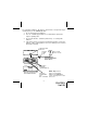
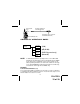
MIC/CHG/SPK JACK VEHICLE CIGARETTE LIGHTER ADAPTER HI LO ADAPTER PLUG (TO VEHICLE LIGHTER RECEPTACLE) MODE GMRS6000-2PK GMRS6000-2PK OPERATIONAL MODES GMRS/FRS (MODE) CHANNEL SELECT (1-22) CTCSS SELECT (oF, 01-38) POWER SELECT (GMRS channels only) ROGER BEEP (on or oF) NOTE: To differentiate between operating modes, look for HI or LO indication below the battery power level indicator when in GMRS mode.
Adjusting the Volume (11, 10) With the unit powered on, press the Up Channel/Volume button ( ) to increase volume and the Down Channel/Volume button ( ) to decrease volume. The display will indicate the current volume level (UL) followed by the number (0-7). As volume is increased upward, the unit will beep at each step, and vice-versa. When the minimum and maximum volume settings are reached, a unique tone will sound.
The PTT Button can also be used as a two-way call ringer. Pressing the button twice quickly will call another party on the same channel. The transmit icon ( ) will be displayed for 3 seconds and then disappear. Up Channel/Volume Button (10) In the standby mode, pressing this button will increment the listening volume. When in function edit mode this button will be used to adjust the unit’s settings.
Operating Modes and Features GRMS/FRS Operation: - Press and hold the Power On/Off button for 2 seconds to turn on power. - Press the MODE button so the Channel number flashes. - Select the desired channel with the Up (10) and Down (11) Buttons. When receiving a call, the icon appears to indicate an incoming call. - Press and hold the PTT button (4) to transmit, then speak into the microphone clearly and slowly. The Transmit icon ( ) appears on the display while the button is pressed.
To change the channel: - From GMRS/FRS standby mode, press the MODE button (12) once; the channel number flashes. - Press the Up Button (10) briefly to move to the next higher main channel number. - Press the Down Button (11) briefly to move to the next lower main channel number. - Press the PTT button momentarily to confirm selection. CTCSS Mode (Sub-Channel) Selection The Coded Tone Controlled Squelch System (CTCSS) has 38 Sub-Frequencies.
Transmit Power Selection Mode (GMRS Channels Only) This feature permits selection of the transmitting power level to high or low when using channels 1-7 and 15-22. Using low power, the unit will have a lower transmit range, but battery life will be increased. NOTE: You will find that for the majority of your needs, the low-power setting will provide adequate communications on all channels; there should seldom be any need to use high power, except in situations where you need absolute maximum range.
Roger Beep Tone The Roger Beep is a tone which is automatically transmitted whenever the PTT button is released and the tone is enabled. This tone alerts the receiving party that the transmission has been terminated intentionally. To enable and disable the Roger Beep tone: - From GMRS standby mode, press the MODE Button 4 times (in FRS mode, 3 times) until the flashing Roger Beep icon ( ) appears with On or oF. - Press the Up or Down Button to select the tone on or off as desired.
Call Ringer Selection Mode The transceiver provides a transmit call ring melody at the receiving unit to alert you to an incoming call. To activate the call ringer melody: - From GMRS/FRS standby mode, press the PTT button twice in quick succession; a call ring melody will sound at the receiving unit to alert the user to an incoming transmission, provided that unit is equipped with this capability and is set to the same channel.
Battery Alert When the battery icon ( ) blinks steadily on the LCD panel, recharge the unit or install fresh batteries. NOTES FOR GOOD COMMUNICATION 1 . The GMRS6000-2PK 22 channels are shared on a ‘take turns’ basis. This means other groups may be talking on any of the channels. A common code of ethics/courtesy is to switch to another vacant channel and not to attempt to talk over someone who is already using the channel you first selected. 2.
Warning • Do not operate the transceiver unless you are licensed to do so. • Remove the batteries from the transceiver if it is not expected to be used for long periods. This will eliminate the possibility of chemicals leaking from the batteries and corroding the transceiver. • Avoid exposing the transceiver to water or extremes of temperature. • Do not use this device in or near a mining facility, which uses remotely triggered explosives or in areas labeled “Blasting Area”.
Troubleshooting Problem Possible cause Correction No transmission while pressing the PTT Button Weak batteries Incorrect battery polarity Charge or replace batteries Install the batteries following the directions in paragraph Installing the Batteries.
Technical Specifications: General Frequency Range: Channels 1 through 7 are shared with FRS radios. Channels 8 through 14 are FRS only. Channels 15 through 22 are GMRS only. Channel Spacing Privacy Codes Dimensions (W x H x D) (Without Antenna) Refer to frequency chart on page 23. Refer to frequency chart on page 23. Refer to frequency chart on page 23. 12.5kHz 38 for each main channel 2.25” W x 3.68” H x 1.125” D (56.0 mm x 93.7 mm x 28.
THIS PAGE LEFT BLANK INTENTIONALLY 21 128-7029 22 of 28
This transceiver complies with FCC regulations for use in the United States of America. Use in other countries may be prohibited or restricted by local regulation. Please check with the local regulating agency before using this device outside the United States of America. Main Channel Frequencies: CHANNEL /TYPE FREQ (MHz ) CHANNEL /TYPE FREQ (MHz ) 1 GMRS/FRS 462.5625 12 FRS 467.6625 2 GMRS/FRS 462.5875 13 FRS 467.6875 3 GMRS/FRS 462.6125 14 FRS 467.7125 4 GMRS/FRS 462.
CHANNELCROSS REFERENCE FOR 14 AND 15 CHANNEL GMRS/FRS RADIO TO 22 CHANNEL GMRS/FRS RADIO CHANNELCROSS REFERENCE FOR 15 CHANNEL GMRS/FRS RADIO TO 22 CHANNEL GMRS/FRS RADIO CHANNEL CROSS REFERENCE FOR 14 CHANNEL FRS RADIO TO 22 CHANNEL GMRS/FRS RADIO 22 C H A N N E L FRS/GMRS 14 C H A N N E L FR S 1 1 1 1 2 2 2 2 3 3 3 3 4 4 4 4 5 5 5 5 6 6 6 6 7 7 7 7 CHANNELS NOT AVAILABLE 22 C H A N N E L FRS/GMRS 8 8 8 9 9 9 10 10 10 11 11 11 12 12 12 13 13 13 14 14 14
Continuous Tone Coded Squelch System Tone Frequencies (in Hz) CTCSS Freq. Hz CTCSS 1 2 3 4 5 6 7 8 9 10 11 12 13 14 15 16 17 18 19 67.0 71.9 74.4 77.0 79.7 82.5 85.4 88.5 91.5 94.8 97.4 100.0 103.5 107.2 110.9 114.8 118.8 123.0 127.3 20 21 22 23 24 25 26 27 28 29 30 31 32 33 34 35 36 37 38 Freq. Hz 131.8 136.5 141.3 146.2 151.4 156.7 162.2 167.9 173.8 179.9 186.2 192.8 203.5 210.7 218.1 225.7 233.6 241.8 250.
90 DAY LIMITED WARRANTY Applies to Audiovox Family Radio and General Mobile Service Products. AUDIOVOX CORPORATION (the Company) warrants to the original retail purchaser of this product that should this product or any part thereof, under normal use and conditions, be proven defective in material or workmanship within 90 days from the date of original purchase, such defect(s) will be repaired or replaced with new or reconditioned product (at the Company's option) without charge for parts and repair labor.
THIS PAGE LEFT BLANK INTENTIONALLY 27 128-7029 27 of 28
© 2004 Audiovox Electronics Corp.