® ELECTRON ICS CORP .
Printer: Leave this page blank -2-
IMPORTANT SAFETY INFORMATION 1) 2) 3) 4) 5) 6) 7) 8) 9) 10) 11) Always unplug the VE500A prior to cleaning. Use only a damp cloth for cleaning. Do not use liquid cleaners or aerosol cleaners. Use only Audiovox approved power adapter to operate the VE500A. Never overload electrical outlets or use extension cords as this can result in a risk of fire or electric shock. Do not install the VE500A product where it is likely to be exposed to water.
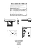
INCLUDED IN THIS KIT 1 2 3 4 5 VE500A 5-Inch Television (P/N 136D2179) (1) Remote Control (P/N 136B2180) (1) AC/DC Power Adapter 12V@1.
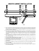
UNDER CABINET INSTALLATION Cabinet or Shelf OPEN 5" TFT LCD TV Bottom Edge Molding AUDIO OX SENSOR AUTO PRO AV/TV PICTURE VOLUME TM CHANNEL P0WER 1) Choose an appropriate mounting location underneath a cabinet or shelf. Close proximity to an electrical outlet and a TV antenna or cable connection will facilitate a neat, easy installation. Do not mount the VE-500A above a range or oven.
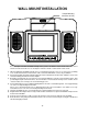
WALL MOUNT INSTALLATION Vertical Mounting Slot (Rear of Unit) AUDIO OX SENSOR AUTO PRO AV/TV PICTURE VOLUME TM CHANNEL P0WER Do not attempt to install the VE-500A vertically, unless you are sure that the electric circuits in the chosen area have been turned off at the fuse or circuit panel. Failure to do this could result in electric shock. 1) 2) 3) 4) 5) 6) 8) 9) When installing the VE-500A vertically, choose a mounting location at or close to eye level.
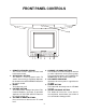
FRONT PANEL CONTROLS OPEN 9 SENSOR AUTO PRO. 1 2 3 PICTURE VOLUME CHANNEL 4 5 6 7 8 6. CHANNEL UP/DOWN BUTTONS These buttons are used to change the channel or make adjustments to the picture quality. Their operation duplicates the CHANNEL UP/ DOWN button on the remote control unit. 7. LED POWER INDICATOR Illuminates whenever power is applied to the VE-500A 8. POWER BUTTON This button will alternately turn the VE-500A on or off. 9.
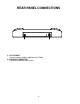
REAR PANEL CONNECTIONS INPUT 1 DC 12V DC 12V INPUT DC LINE OUT OUTPUT DC AUDIO R INPUT 2 VIDEO L VIDEO AUDIO R ANT. DC L 2 1 1) 12V DC INPUT Connect to power adapter supplied with VE-500A. 2) ANTENNA CONNECTOR Connect to antenna or cable system.
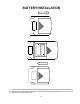
BATTERY INSTALLATION 1) Turn the Remote Control face down. Press down on the ridged area of the battery cover and slide it off. 2) Install the two “AAA” batteries included as shown. Make sure that proper polarity (+ or -) is observed. 3) Slide the cover back until it clicks.
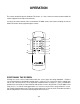
OPERATION The remote control will operate Audiovox Televisions. It is not a universal remote control and will not control equipment from other manufacturers. If a universal remote control is to be used with the VE-500A, choose the remote encoding scheme for Action Televisions when programming the remote.
REMOTE CONTROL FUNCTIONS 1. POWER ON/OFF Press this button to turn on the TV. The channel number or current video source will be displayed on screen, and the picture will appear in a few seconds. Press the button again to turn the TV off. 2. NUMERICAL BUTTONS Use these buttons to make a direct channel selection. The channel number chosen will be displayed on the screen for 4 seconds. Channel selection is carried out with 0-9 keys (0-99ch) and “1—“ key when in cable mode (100-125ch). 3.
CHANNEL TUNING SET UP In addition to normal broadcast reception of VHF and UHF channels, if you are a Cable TV subscriber, your new VE500A is capable of receiving many unscrambled Cable channels without the use of a converter box. When set to Broadcast TV it receives CH2-CH69. When set to one of the CATV modes (STD, HRC, or IRC) it receives CH1-CH125. Follow this simple procedure to make channel tuning more convenient. 1.
TROUBLESHOOTING Problem Solution Poor Reception Verify Tuner setting matches Antenna / Cable broadcast system. Try other system types with the TV/CATV BUTTON of the remote control. Remote control will not function Verify that the sensor on the VE-500A is not obstructed. Verify that the infrared LED on the transmitter is not obstructed. Check the condition of the remote control batteries. Black and White Reception Verify Tuner setting matches Antenna / Cable broadcast system.
TECHNICAL SPECIFICATIONS Illumination: Edge Light Tube Backlighting Life Expectancy: 10,000 Hrs. Pixels: 224,640 Resolution: 960 X 234 Power Supply: 12 Volts + or - 10% @1.3-1.5 A Operating Temperature: 0° - 40°C Storage Temperature: -20° - 80° C Sensitivity: 35 db Video System: NTSC Audio output: 1.
This Page intentionally left blank -15-
90 DAY LIMITED WARRANTY Applies to Audiovox Video Products AUDIOVOX ELECTRONICS CORP. (the Company) warrants to the original retail purchaser of this product that should this product or any part thereof, under normal use and conditions, be proven defective in material or workmanship within 90 days from the date of original purchase, such defect(s) will be repaired or replaced with reconditioned product (at the Company's option) without charge for parts and repair labor.