® VDS102T DROP-DOWN VIDEO MONTOR ON OFF AUTO Installation Guide
Important Notice An LCD panel and/or video monitor may be installed in a motor vehicle and visible to the driver if the LCD panel or video monitor is used for vehicle information, system control, rear or side observation or navigation. If the LCD panel or video monitor is used for television reception, video or DVD play, the LCD panel or video monitor must be installed so that these features will only function when the vehicle is in “park” or when the vehicle’s parking brake is applied.
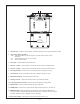
MATERIALS INCLUDED IN THIS PACKAGE: 1) 2) 3) 4) 5) 6) 7) 8) Over Head Docking Station (P/N 136-3955) – (1 pc) Lamp Harness (P/N 112B3110) – (1 pc) 2 Pin Power Wire Harness with choke (P/ N 112B3143) – (1 pc) Hardware Package Screws (#4) – (8 pcs) Self Drilling Screws (#8) – (4 pcs) Nut – (4 pcs) Trim Ring (P/N 102-4111) – (1 pc) PODTVT (P/N 136-3877) – (1 pc) Mounting Bracket (P/N 108-3856) – (1 pc) Remote Control (P/N 136-3956) – (1 pc) 1 2 3 ON OFF AUTO 4 7 6 5 8 POWER SOURCE AUTO MEMORY SKIP
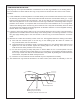
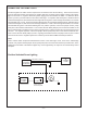
1 2 3 12 4 5 6 7 8 11 9 14 13 10 1. Infrared Sensor – Allows the remote control to operate the VDS102T and to control the shuttle when docked. 2. Three position Dome Light Switch • Auto – Automatically switches on the dome lights in conjunction with the vehicle’s interior illumination. • Off – The dome lights will not turn on in this position. • On – Turns on the dome lights. 3. Dome Lights – Provide additional interior illumination. 4.
GENERAL INSTALLATION APPROACH: 1) Decide upon system configuration and options that will be installed (i.e.: what components, VCP, Video Game, external amp, wireless headphones, etc.). 2) Review all manuals to become familiar with electrical requirements and hook ups. 3) Decide upon mounting locations of all components and method of mounting.
VEHICLE PREPARATION: 1) Locate an accessory power source (+12v when key is in the ACC. and run positions, and 0v when key is off), and also a good ground generally, these wires can be found at the ignition switch or fuse-box. 2) The mounting method and location will vary from vehicle to vehicle, so this manual will only focus on the installation of the video monitor and related console accessories. 3) Generally, the best location for the video monitor is where the vehicle's factory dome light is installed.
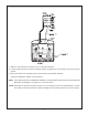
TRIM RING INSTALLATION: This page only covers special installation considerations for the trim ring installation. If the docking station is to be installed in a vehicle with the trim ring, it may need to be trimmed to fit the contour of the vehicle headliner. 1) In this installation, the docking station is mounted directly to the overhead cross-member in the roof using the mounting screw bosses. These screw bosses should contact the cross-member directly (i.e.
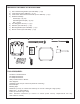
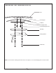
MOUNTING THE TRIM RING VDS102 Roof Roof Support Headliner Mounting Bracket (4) Self-Tapping Screws Trim Ring Docking Station (4) M5 Nuts NOTE: Use care when screwing the bracket to the roof support, so to avoid damaging the roof of the vehicle ~6~ ~6~
` 1) Make the connections to the vehicle for the 12 pin wiring harness. 2) Connect power harness to vehicle’s electrical system by tapping into an accessory hot line and a good ground. 3) Verify all functions of the System before final mounting of the finished assembly. A/V Source Definitions: Shuttle, AV Input and TV *NOTE: If the original relay box P/N SIRSWB is installed, it recommended that the antenna for the wireless FM Modulator be unplugged. See Figure A for antenna location.
CONNECTING THE DOME LIGHTS The dome lights in the video monitor require three connections to the vehicle's wiring. There are two common types of dome light circuits used, positive or negative switched. Positive systems supply voltage to the interior lights to turn them on, negative switched systems apply ground to illuminate the bulbs. To determine which system you have you must locate the wires at the dome light.
Negative Switched Dome Lighting To 12 pin connector Red / black - Lamp on Black / red - Lamp common Purple / brown - Lamp Auto To constant To constant Factory Door ajar switch or Body Control computer Troubleshooting: SYMPTOM: REMEDY: No power at Video Monitor Verufy +12 VDC on Red wire at 2 pin Power Harness behind video monitor.
For Customer Service Visit Our Website At WWW.audiovox.com Product Information, Photos, FAQ’s Owner’s Manuals 128-7347 © Copyright 2005 Audiovox Electronics Corp. 150 Marcus Blvd.