PROFESSIONAL SERIES Remote Keyless Entry Installation Guide ca 2051 ca2051 rev B. 2011 Audiovox Electronics Corporation. All rights reserved.
Table of Contents Before You Begin ...................................................................................... 3 Wire Connection Guide ........................................................................... 4 10 Pin Main Harness ................................................................................. 5 6 Pin Door Lock Harness .......................................................................... 8 Additional Ports ...............................................................
BEFORE YOU BEGIN PROFESSIONAL INSTALLATION STRONGLY RECOMMENDED Installation Precautions: Roll down window to avoid locking keys in vehicle during installation Avoid mounting components or routing wires near hot surfaces Avoid mounting components or routing wires near moving parts Tape or loom wires under hood for protection and appearance Use grommets when routing wires through metal surfaces Use a Digital Multi Meter for testing and verifying circuits.
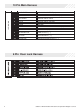
10 PIN MAIN 10 Pin Main Harness 1 BLUE/GREEN 2ND UNLOCK OUTPUT ( - ) 2 BLACK/WHITE ILLUMINATED ENTRY OUTPUT ( - ) 3 WHITE/RED PARKING LIGHT INPUT 4 WHITE PARKING LIGHT OUTPUT 5 BLACK GROUND 6 ORANGE GROUND WHEN ARMED OUTPUT ( - ) 7 RED BATTERY 12V ( + ) 8 BROWN/BLACK HORN OUTPUT ( - ) 9 YELLOW IGNITION INPUT ( + ) 10 RED/WHITE TRUNK RELEASE OUTPUT ( - ) 6 Pin Door Lock Harness 4 ca2051 rev B. 2011 Audiovox Electronics Corporation. All rights reserved.
10 Pin Main Harness 1 BLUE/GREEN 2ND UNLOCK OUTPUT ( - ) This wire provides a ( - ) 200mA output upon the second press of unlock. This output is used unlock the remaining passenger doors when the system is set up for driver priority unlock. 2 BLACK/WHITE ILLUMINATED ENTRY OUTPUT ( - ) This wire provides a ( - ) 200mA output for 30 seconds when the system is disarmed capable of driving relays. Locate the vehicle’s dome light or pin switch wire.
5 BLACK GROUND Connect the BLACK wire to a solid chassis ground point using a ring terminal and self tapping screw (not supplied). Scrape away paint from the grounding point to ensure a good connection. The recommended grounding point is a metal surface in the driver’s side kick panel area. NOTE: Do not ground the BLACK wire with any other vehicle components. 6 ORANGE GROUND WHEN ARMED OUTPUT ( - ) This wire will have a continuous ( - ) 500mA output when the system is Armed.
9 YELLOW IGNITION INPUT ( + ) Locate the vehicle’s ignition wire at the ignition switch. Verification: This wire registers voltage when the key is turned to the ON (or RUN) position. The voltage does not drop out when the key is turned to the START (or CRANK) position. Connect the YELLOW wire to the vehicle’s Ignition wire. 10 RED/WHITE TRUNK RELEASE OUTPUT ( - ) Locate the vehicle’s trunk release wire at the trunk release switch.
6 Pin Door Lock Output Harness 1 BROWN/BLACK UNLOCK SWITCH ( 87A ) 2 BLUE/BLACK UNLOCK MOTOR ( 30 ) 3 VIOLET/BLACK UNLOCK POLARITY ( 87 ) 4 WHITE/BLACK LOCK SWITCH ( 87A ) 5 GREEN/BLACK LOCK MOTOR ( 30 ) 6 VIOLET LOCK POLARITY ( 87 ) The door lock / unlock outputs are designed to control several different types of systems which may require additional parts.
Additional Ports LED Port The LED included in the kit will serve as a visual indicator of the alarm’s status. It should be installed in the dash, located where it can be easily seen from outside the vehicle, yet not be distracting to the driver. Once a location has been selected, check behind the panel for wire routing access, and to confirm the drill will not damage any existing components as it passes through the panel.
Set Up & Programming Transmitter Programming - Feature Bank 1 1. Turn the ignition ON. 2. Press and hold the valet/override button. 3. Within 10 seconds the system will chirp (3) three times. 4. Press 1 button of each transmitter you wish to program. 5. The system will respond with 1 chirp for each accepted transmitter. 6. Pressing the override button at anytime during programming will advance to the next bank. NOTE: The system will exit transmitter programming after 15 seconds of inactivity.
Feature Bank 1 - 3 Chirps Transmitter Programming Refer to transmitter programming. Feature Bank 2 - 4 Chirps Security Control 1 LED Flash 2 LED Flash Silent Choice ON OFF Feature Bank 3 - 5 Chirps Output Control 1 LED Flash 1 Extended Lock Pulse 2 3 LED Flash 4 LED Flash 5 LED Flash 2 LED Flash 3 LED Flash 4 LED Flash 5 LED Flash 1 Second 3.
Feature Descriptions Feature Bank 2 - Security 1 - Silent Choice: Controls the normal arm/disarm chirps of the security system. ON - Silent arming/disarming upon first press of lock/unlock, pressing lock/ unlock a second time will activate the arm/disarm chirps respectively. The system will only sound the arm/disarm chirps upon a second press of the lock/unlock buttons. OFF - normal arm/disarm chirps upon the first press of lock/unlock.
4 - Trunk Output Timing - Red/White Output: Control of the RED/WHITE trunk release output wire when trunk release is activated from the transmitter. Push and Hold - Output is continuously active until transmitter button is released. 10 Seconds - Output stays active for 10 seconds regardless of length button press on transmitter. 20 Seconds - Output stays active for 20 seconds regardless of length button press on transmitter. Latched until IGN ON - Output stays active until the ignition is turned on.
ca2051 rev B. 2011 Audiovox Electronics Corporation. All rights reserved.
ca2051 rev B. 2011 Audiovox Electronics Corporation. All rights reserved.
Audiovox Electronics Corporation. Customer Service 1-800-421-3209 WWW.CODE-ALARM.COM FCC COMPLIANCE This device complies with Part 15 of the FCC rules and with RSS-210 of Industry Canada. Operation is subject to the following two conditions: 1. This device may not cause harmful interference, and 2. This device must accept any interference received, including any interference that may cause undesired operation.