In-Vehicle Wireless Observation System Kit Owner’s/Installation Manual WOS500 Audiovox Specialized Applications, LLC 23319 Cooper Drive Elkhart, IN 46514 (219) 264-3135 Page 1 of 12 Rev.
Contents: 1) 2) 3) 4) WOS500T Transmitter WOS500R Receiver Power Harness with Locking Connector Hardware Package Before Installation: • This system operates on 12 Volts DC only, negative ground • For maximum operating range, try to minimize the number of obstacles between the transmitter and receiver units. • This system broadcasts high-quality audio and video, using directional antennas that must be orientated in certain configurations for best results.
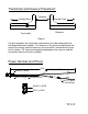
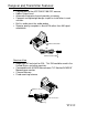
Transmitter and Receiver Placement: Antenna Vehicle Rear Vehicle Front Receiver Transmitter Figure 1 For best reception the transmitter and receiver must be aligned with the flat-pitted faces back to back. The antenna in the receiver should face the rear of the vehicle and the antenna in the transmitter should face the front of the vehicle. RF signal can be picked up between the receiver and the transmitter best by using this method. Power Harness and Pinout: 58.
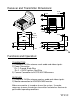
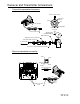
Receiver and Transmitter Dimensions: 0.195 TYP. 0.098 0.478 0.478 0.098 0.293 1.833 1.443 0.117 TYP.4 0.975 0.195 R0.585 TYP. 2 0.293 1.365 0.078 0.585 1.112 0.303 0.293 0.156 2.340 Transmitter Feature Only 1.463 Functions and Operation: TRANSMITTER 1) Directional 2.4GHz antenna sends audio and video signals. 2) Power Connection Pin 1- Ground- Black Wire Pin 2- +12VDC ignition- Red Wire 3) Camera Connection to AOC75/AOC100 camera. RECEIVER 1) Directional 2.
Receiver and Transmitter Features: Transmitter View • Connectable to the AOC75/AOC100 CDC camera • 0 dBm Output Level • Automatic electronic channel provides a memory • Compact and lightweight design simplifies installation in most vehicles. • Built-in audio circuit for audio pickup • Superior quality reception is due to FM rather than AM signal modulation. Power Connection 96" Camera Connection Receiver View • Adapt high RF technical for EIA.
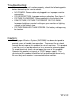
Receiver and Transmitter Connections: Transmitter connection to camera Arrow Locking Location Video From Camera Audio 12V Power Connection Ground/Shield Cable Connector End View 96" Camera Connection Wind Deflector Installation Optional EMI Ferrite Core Waterproof Camera Connector Transmitter Cable Connector To Transmitter Grommet To Seal Through Vehicle Exterior Receiver connection to monitor Video +12V Video Line Shield Ground Audio Receiver Connection End View 120" 12" 12" Monitor Connection
Troubleshooting: If the system does not function properly, check the following points before contacting the service center. • NO POWER- Power cable not plugged in or improper monitor connection • POOR RECEPTION- Improper antenna direction. See figure 1. • PICTURE FLICKERING- Strong spotlight in the field of view • DIM PICTURE, PICTURE TOO BRIGHT OR TOO DARKImproper brightness control setting on your monitor or lighting source in the field of view.
Maintenance: • Remove dust and dirt with a damp soft cloth. • Heavier dirt should be removed with a damp cloth and a mild detergent. • Do not use strong cleaning agents containing gasoline, thinner, benzene or alcohol. Hardware Package Contents: Quantity 8 Screw, #4 x 3/4" Pan Head Phillips, Self-Drilliing Page 8 of 12 Rev.
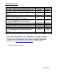
Accessory List: Description AVT-988 9”Color Television with Remote (12V) AVT-597 5”Color Television with Remote (12V) AVT-1498 13”Color Television with Remote (12V) AVP-7000 Video Cassette Player (12V) BPA-501-12 4 Amp Adapter for use with AVT988 9”and AVT-1498 13”Televisions AC2A- 2 Amp Adapter for use with AVT-597 5” TV and AVP-7000 Video Cassette Player Unified Remote Control VAC-21- 12 Volt Corded Vacuum AVF-1 12 Volt Rechargeable Flashlight HP-175 Headphones with Pivoting Ear Cup HP-275 Headphones with
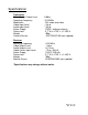
Specifications: Transmitter Video Carrier Output Level Operating Frequency Modulation Video Input Level Audio Input Level Power Supply Dimensions Weight Camera Device Receiver Receiving frequency Video Output Level Audio Output Level Video Carrier Input Level Power Supply Dimensions Weight Monitor Device 0 dBm 2410 MHz FM- audio and video 1 Vp-p 1 Vp-p 12VDC, (without camera) 3.7”W x 4.725”L x 2.165”H 300g AOC75/AOC100 (not supplied) 2410 MHz 1 Vp-p 0.1 Vrms -75 to –30 mA 12VDC, 320 mA 3.7”W x 4.
Notes: ______________________________________ ______________________________________ ______________________________________ ______________________________________ ______________________________________ ______________________________________ ______________________________________ ______________________________________ ______________________________________ ______________________________________ ______________________________________ ______________________________________ _____________________________________
Page 12 of 12 Rev.