
Installation guide

ADVANCED MANUAL / bit Ten D /
33
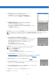
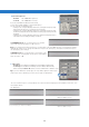
The Selected Input window shows the source that is active while the bit Ten D is
connected to the PC. You can select the desired source by clicking it. Once the
bit Ten D has been disconnected from the PC, you can select the bit Ten D
input source through the DRC
(see 10 ).
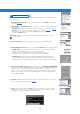
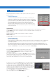
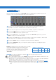
This window displays the names given to the output channels.
When this window is active, you can manage each channel that, once selected,
will be highlighted.
Press the CTRL key and click another channel to select and highlight it as well.
The filter curve will appear on the graph at the same time.
Multiple selection is only allowed for functional groups, except for the
Subwoofer that can be selected with any group.
E.g. Front Left Full can be selected with Subwoofer but not with Rear Left Full.
If you want to check the Rear + Subwoofer system, you have to de-select the
Front system.
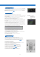
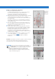
The software only allows you to work on a single channel and will display the
word EDIT in red next to the corresponding channel.
In particular, the graph will display a red line for only the electrical response of
the crossover corresponding to the editing channel, a blue line for the overall
electrical response of all selected channels, taking into account the crossover
filters and equalizations, and a green line for the final result.
To act on another channel and keep your selection, click to the right
of the desired channel, where the EDIT column is.
The CHANNEL MAP window also lets you silence each channel by clicking
on the word MUTE to the left of the desired channel.
If MUTE is on, the word gets highlighted in green.
You can also select a channel as shown in the image next
to the following chapter 8.9.
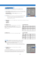
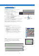
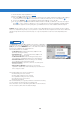
This window is active. You can click the speakers or the
speaker system to manage each single channel that, once selected,
will be shown highlighted. If you keep the CTRL key pressed and click
on another channel, this other channel will be selected and highlighted
as well, similarly to what happens with the Channel Map
(see 8.8).
Listening point visual indicator
The Select Channel window includes this function as well (shown in green).
Four points are pre-set: driver, passenger, front center and
rear center for the corresponding passengers.
This indication acts only and exclusively as a reference for the
digital delay automated calculation
(see 8.11)
. If delays are set
according to the “driver” position and then you want to optimize
the system also for the “passenger” position, you need to set
the distances through the specific menu
(see 8.11)
again, as the
system doesn’t update them automatically.
If used together with the presets
(see 8.14)
, it is useful to
try different setups according to the different listening points.
8
8.8 CHANNEL MAP
5
8.7 SELECTED INPUT
4
8.9 SELECT CHANNEL
6
Remark: The channels
highlighted in green
are dedicated to
the AD Link digital
output.