
Users Manual

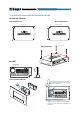


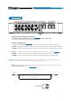
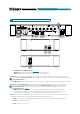
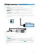
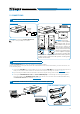
Table Of Contents
- Index
- 1. PRODUCT DESCRIPTION
- 2. PACKAGING CONTENTS
- 3. bit One HD Virtuoso AND DRC MP INSTALLATION
- 4. CONNECTION PANELS - DESCRIPTION
- 5. CONNECTIONS
- 6. bit One HD Virtuoso SOFTWARE AND DRIVERS - INSTALLATION GUIDE
- 7. bit One HD Virtuoso SETUP WITH PC
- 8. bit One HD Virtuoso SETUP USING A PC
- 9. TROUBLESHOOTING
- 10. TECHNICAL SPECIFICATIONS
- 11. ADDENDUM

5
USER'S MANUAL
1. SPEAKERS IN hi-level MASTER input (see section 5.5)
Ch1 - Ch2 - Ch3 - Ch4 - Ch5 - Ch6 - Ch7 - Ch8 - Ch9 - Ch10 - Ch11 - Ch12
HI LEVEL MASTER inputs to connect the amplied signal wires coming from the main analog
source. Input sensitivity automatically adjustable from 2 to 15 V RMS
(see sec. 7.2.4).
Channels Ch1 - Ch2 feature the AUTO TURN ON (ART) function through the connection with the source
speakers outputs. This function can be excluded using the PC software
(see section 7.2.2.2).
The input signals are interfaced to the bit One HD Virtuoso via wiring with a multi-pin 24 poles connector as
described below.
4. CONNECTION PANELS - DESCRIPTION
4.1 INPUT SIGNALS
Remark:
when connecting a speaker input cable, use Faston crimp terminals.
320 mm / 12.6 in.
Wire Size: AWG
80 mm / 3.15 in.
10 mm / 0.39 in.
FRONT VIEW
13
14
15
16
17
18
19
20
21
22
23
24
1
2
3
4
5
6
7
8
9
10
11
12
2 31
4
SDCDRCC
4
IN 3IN 3
IN 2IN 2
IN 1IN 1
IN 4IN 4
IN 5IN 5
IN 6IN 6
IN 7IN 7
IN 8IN 8
IN 9IN 9
IN 10IN 10
IN 12IN 12
IN 11IN 11
IN 3IN 3
IN 2IN 2
IN 1IN 1
IN 4IN 4
IN 5IN 5
IN 6IN 6
IN 7IN 7
IN 8IN 8
IN 9IN 9
IN 10IN 10
IN 12IN 12
IN 11IN 11
1: white IN1+
13: gray IN1-
2: white IN2+
14: gray IN2-
3: white IN3+
15: gray IN3-
4: white IN4+
16: gray IN4-
5: white IN5+
17: gray IN5-
6: white IN6+
18: gray IN6-
7: white IN7+
19: gray IN7-
8: white IN8+
20: gray IN8-
9: white IN9+
21: gray IN9-
10: white IN10+
22: gray IN10-
11: white IN11+
23: gray IN11-
12: white IN12+
24: gray IN12-
MASTER INPUTS