
Users Manual

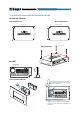


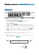
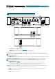
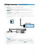
Table Of Contents
- Index
- 1. PRODUCT DESCRIPTION
- 2. PACKAGING CONTENTS
- 3. bit One HD Virtuoso AND DRC MP INSTALLATION
- 4. CONNECTION PANELS - DESCRIPTION
- 5. CONNECTIONS
- 6. bit One HD Virtuoso SOFTWARE AND DRIVERS - INSTALLATION GUIDE
- 7. bit One HD Virtuoso SETUP WITH PC
- 8. bit One HD Virtuoso SETUP USING A PC
- 9. TROUBLESHOOTING
- 10. TECHNICAL SPECIFICATIONS
- 11. ADDENDUM

7
USER'S MANUAL
321
4
1. PRE OUT low-level analog signal (4 Volt RMS) (see section 5.7.2)
Ch1 - Ch2 - Ch3 - Ch4 - Ch5 - Ch6 - Ch7 - Ch8 - Ch9 - Ch10 - Ch11 - Ch12 - Ch13
To connect the RCA cables going to the system’s ampliers.
2. AD Link - OUT digital signal
(see section 5.7.1)
S/PDIF standard digital signal (Ch1÷Ch13) to connect ampliers provided with the specic AD Link input.
AD LINK 1: S/PDIF standard digital signal (Ch1÷Ch8) to connect ampliers provided with the specic AD Link input
AD LINK 2: S/PDIF standard digital signal (Ch9÷Ch13) to connect ampliers provided with the specic AD Link input
3. AC Link: Connection socket to control the ampliers provided with AC Link connection (see section 5.7.1).
AC LINK 1: Connection socket to control the ampliers (Ch1÷Ch8) provided with AC Link connection.
AC LINK 2: Connection socket to control the ampliers (Ch9÷Ch13) provided with AC Link connection.
4. RVA (Remote Volume Aux): control signal output to connect to the master source AUX input, to enable the
“AIS - Auto Input Switch” function.
(see 5.4.3 - 5.6.1; 8.3.5).
Remark: the Remote Out signal is available on the AC LINK 1 / AC LINK 2 connection plugs and is active to the
ampliers supporting this function (Audison AV ampliers with AV bit IN input).
RCA / Jack
stereo Adapter
Included
4.2 OUTPUT SIGNALS
4500 mm / 177.17 in.
4