M3 Installation Guide TRI-ELEMENT HANGING CEILING MICROPHONE Installation Guide
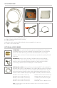
IN THE PACKAGE 1 1 2 3 4 5 2 3 4 5 M3 Tri-element Hanging Ceiling Microphone JBM3 - Plenum rated junction box circuitry Junction box lid Breakout cable consisting of RJ45 female to three terminal block connectors Seismic / Fire restraint cable OPTIONAL ACCESSORIES 6 PLENHSEM3 brass plenum bell housing (patent pending). This brass housing is specifically designed to provide a plenum seal when threaded on to the plenum junction box.
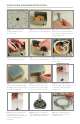
INSTALLATION AND WIRING INSTRUCTIONS Fig A. Remove ceiling tile and drill 5/8” (16mm) hole in the desired location. Fig B. Position the JBM3 plenum rated junction box 2 over the drilled hole. Fig C. Remove the nut from the threaded portion of the M3 cable 1 , feed cable through the tile hole and into the junction box. Fig D. Install the threaded nut with shoulder side down and secure. Fig E. Insert the 7 pin mini female XLR Fig F. Set the initial height of the M3 connector into the male receptacle.
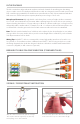
IN THE PACKAGE The M3 contains three independent microphones and audio channels for interfacing into the mixing device or audio console. The Audix provided breakout cable 4 is designed to interface with a professional DSP controller using terminal blocks. Audix has an optional breakout cable 7 that terminates with three XLR connectors. The M3 microphone requires phantom power voltage of 18-52 volts.