
Installation Guide
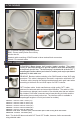
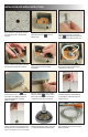
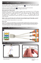

Fig A. Remove ceiling tile and drill
5/8” (16mm) hole in the desired
location.
Fig B. Position the JBM3 plenum
rated junction box over the
drilled hole.
Fig C. Remove the nut from
the threaded portion of the M3
cable , feed cable through the
tile hole and into the junction box.
Fig D. Install the threaded nut with
shoulder side down and secure.
Fig E. Insert the 7 pin mini female
XLR connector into the male
receptacle.
Fig F. Set the initial height of the
M3 and spool the excess cable
inside the junction box.
Fig I. Adjust the cable to exact
desired length by either feeding
or pulling the cable through the
ceiling mount.
Fig G. Fasten the lid on top
of the junction box. Insert RJ45/
Cat cable into JBM3 receptacle.
(See back page for installing
seismic cable)
Fig H. If using Audix Cat 7 LSOH
interface cable , screw on the
brass bell housing over the RJ45
connection and reset ceiling tile.
Fig K. Microphone elements are
spaced 120 degree apart. Channel
1 is directly below the Audix logo
Fig J. Position the microphone by
turning the cable as necessary and
gently turn the nut clockwise to se-
cure (1 to 2 turns). Do not over tighten.
INSTALLATION AND WIRING INSTRUCTIONS
Fig L. Connect RJ45 cables into
the breakout cable and connect to
DSP Controller.
1
8
3
2