* + ----- !" #$% & '' ( $) )) !" #$ % & '' ( , ) + + . + + / Single-Button Microphone Unit (SMU1) Incorporating Microphone Pre Amplifier (MPAB3) User Manual V1.3 page 1 of 15 21016 SMU1-MPAB3 V1.3.
Revision History Version 1.0 1.1 1.2 1.3 Modifications Original issue. First Revisions Cable Type Changed Connection Details Added Date 19/07/01 26/09/01 21/10/05 16/12/05 © Copyright Audix Systems. 2005 DISCLAIMER This manual contains information that is correct to the best of Audix Systems knowledge. It is intended to be a guide and should be used as such.
Models Covered This user manual covers the following equipment • • SMU1 (570.005.005) Single Button Paging Microphone MPAB3 (570.005.007) Microphone Pre Amplifier Technical Support In the unlikely event of you having problems with your SMU 1 please contact our Technical Support. Audix Systems Station Road Wenden Saffron Walden CB11 4LG Tel +44 (0)1799 540888 Fax +44 (0)1799 541618 Website www.tycosafetyproducts-europe.com, www.audixsystems.co.uk page 3 of 15 21016 SMU1-MPAB3 V1.3.
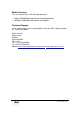
Table of contents Revision History.......................................................................................................2 Models Covered ...........................................................................................3 Technical Support ........................................................................................3 Table of contents..........................................................................................4 Product Description ............................
Product Description The SMU1 is desk mounted microphone console for primarily designed for use with Audix Systems Public Address and Voice Alarm controllers. Led indicators provide comprehensive status display. Red LED’s showing when zones are busy, green LED’s show when calls are successful. The SMU1 features a good quality dynamic microphone, chosen for its clear and natural sound.
control applied by the compressor so that an approximately constant level of surveillance tone is always available at the output. A chime circuit (ding-dong) may be optionally triggered from the control input (e.g. Press to talk switch) and if used gives a logic level output which is intended to flash an led during the chime and switch it continuously on when the microphone is enabled.
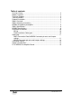
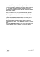
SMU1 Overview The microphone comprises; • Desk mount microphone unit with PTT (Press To Talk Button) • Speak indicator (Green) • Busy indicator (Red) • Goose neck Microphone • Microphone pre-amplifier unit in separate junction box (MPAB3) SMU 1 SMU1 Operating instructions Operation LIVE broadcast • When the SMU is idle the red LED will show if the system is busy. • To make an announcement the user is to press and hold the Speak button. Until this point announcer has had no effect on the PA system.
MPAB3 microphone preamplifier The MPAB3 pre amplifier is used with SMU1 or handheld microphones. These are the only Audix microphones without an integral pre amp/line amplifier. The MPAB3 is housed in a metal box and will require fixing near to the microphone. The box is fitted with glands. It is the responsibility of the installer to ensure the cables are glanded correctly.
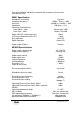
Each pair should be individually screened, with a common overall screen connected to earth. SMU1 Specification Microphone Technology Frequency Response Sensitivity Impedance Directional Characteristics: From 200Hz – 2kHz From 2kHz – 5kHz Switch (Max DC switching current) LED current Requirment (24V DC) Busy Indication Speak Indication Cable Length (Filotex) Dynamic 150Hz – 7kHz (+/- 3dB) -83.
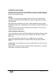
Installation Instructions Warning: Upon first connection of the SMU1 to a system, the initial setting of the 20kHz surveillance tone is set at the factory and may need to be adjusted during system commissioning. Wiring. The SMU1 will normally be located on a desk or table, but is permanently wired into a junction box/wall box/MPAB3 using the single flexible multi core cable provided.
Setting Up. There are a number of pre-set controls that must be set during system commissioning. The location of these controls is shown in the figure below. Use the channel gain control on the PA system to adjust the volume of the microphone. Do not adjust the “mic pre-set gain control” which has been factory set to match the characteristics of the microphone, and will not normally be adjusted on site. The “chime switch” will be set to select the required chime.
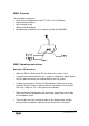
MPAB3 Connector pin-outs and Jumper settings MPAB3 Wiring MPAB3 Connection Details MPAB3 (D718) Jumper settings Omit 2 tone chime J1 Fit 3 tone chime J2 Omit Enable Chime Fit Disable Chime J3 Omit Ptt Operation, Active Low (Fit J5) Fit Ptt Operation, Active High (Omit J5) J4 Omit Normal Operation Fit Permanently Enable Pre Amplifier J5 Omit Ptt Operation, Active High (Fit J3) Fit Ptt Operation, Active Low (Omit J3) J6 Omit Power Off Fit Power On J7 Omit A1 > A1 Fit A1 > SCREEN MPAB3 Trim Pot Settings VR1
Connection Details page 13 of 15 21016 SMU1-MPAB3 V1.3.
Safety Considerations. Review the following safety precautions to avoid injury and prevent damage to the product. The product should only be used as specified. The SMU1 should be operated from a suitable DC supply of nominally 24V. Use only the correct power source, which must contain current overload protection to protect the wiring between the system and the SMU1. Do not disconnect the cable from the product whilst the Voice Alarm system is powered.
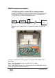
D718 MPAB3 Pre Amplifier Board page 15 of 15 21016 SMU1-MPAB3 V1.3.