Electric part-turn actuators SG 05.1 – SG 12.1 SGR 05.1 – SGR 12.
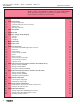
Part-turn actuators SG 05.1 – SG 12.1 / SGR 05.1 – SGR 12.1 AUMA NORM Scope of these instructions: These instructions are valid for part-turn actuators of the type ranges SG 05.1 – SG 12.1 and SGR 05.1 – SGR 12.1 in version AUMA NORM. These operation instructions are only valid for “clockwise closing”, i.e. driven shaft turns clockwise to close the valve. Table of contents 2 Operation instructions Page 1. Safety instructions 1.1 Range of application 1.2 Commissioning (electrical connection) 1.
Operation instructions Part-turn actuators SG 05.1 – SG 12.1 / SGR 05.1 – SGR 12.1 AUMA NORM 13. Setting the DUO limit switching (option) 13.1 Setting direction CLOSE (black section) 13.2 Setting direction OPEN (white section) 13.3 Checking the DUO limit switches 17 17 17 17 14. Setting the torque switching 14.1 Setting 14.2 Checking the torque switches 18 18 18 15. Test run 15.1 Checking the direction of rotation 15.2 Checking the limit switching 19 19 19 16.
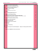
Part-turn actuators SG 05.1 – SG 12.1 / SGR 05.1 – SGR 12.1 AUMA NORM Operation instructions 1. Safety instructions 1.1 Range of application AUMA actuators are designed for the operation of industrial valves, e.g. butterfly valves and ball valves. For other applications, please consult us. The manufacturer is not liable for any possible damage resulting from use in other than the designated applications. Such risk lies entirely with the user.
Operation instructions 3. Part-turn actuators SG 05.1 – SG 12.1 / SGR 05.1 – SGR 12.1 AUMA NORM Technical data Part-turn actuators AUMA NORM require external controls. AUMA offers actuator controls AUMA MATIC AM or AUMATIC AC. These can also easily be mounted to the actuator at a later date.
Part-turn actuators SG 05.1 – SG 12.1 / SGR 05.1 – SGR 12.
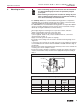
Part-turn actuators SG 05.1 – SG 12.1 / SGR 05.1 – SGR 12.1 AUMA NORM Operation instructions 4. Transport, storage and packaging 4.1 Transport Fitting the ball handle: .. . For transport to place of installation, use sturdy packaging. Do not attach ropes or hooks to the handwheel for the purpose of lifting by hoist. If part-turn actuator is mounted on valve, attach ropes or hooks for the purpose of lifting by hoist to valve and not to part-turn actuator.
Part-turn actuators SG 05.1 – SG 12.1 / SGR 05.1 – SGR 12.1 AUMA NORM 5. Operation instructions Manual operation The actuator may be operated manually for purposes of setting and commissioning, and in case of motor failure or power failure. Engaging manual operation: Manual operation is activated by pulling at the handwheel. A change-over is not required. The handwheel does not rotate during motor operation. . .
Part-turn actuators SG 05.1 – SG 12.1 / SGR 05.1 – SGR 12.1 AUMA NORM Operation instructions 6. . . Mounting to valve . . .. . .. . . Prior to mounting, the part-turn actuator must be checked for any damage. Damaged parts must be replaced by original spare parts. After mounting, check part-turn actuator for damage to paint finish. If damage to paint-finish has occurred after mounting, it has to be touched up to avoid corrosion.
Part-turn actuators SG 05.1 – SG 12.1 / SGR 05.1 – SGR 12.1 AUMA NORM 7. Electrical connection 7.1 Connection with AUMA plug/socket connector Figure C-1: Connection 50.0 50.01 51.0 51.
Part-turn actuators SG 05.1 – SG 12.1 / SGR 05.1 – SGR 12.1 AUMA NORM Operation instructions 7.4 Controls made by AUMA In case the required reversing contactors are not to be installed in the control cabinet, the controls AUMA MATIC or AUMATIC can easily be mounted to the actuator at a later date. For enquiries and more information, please state our commission no. (refer to actuator name plate). 7.5 Heater AUMA part-turn actuators have a heater installed as standard.
Part-turn actuators SG 05.1 – SG 12.1 / SGR 05.1 – SGR 12.1 AUMA NORM 8. Operation instructions Setting the end stops for part-turn actuators on butterfly valves For actuators on ball valves refer to page 13, section 9. The settings can only be performed if the valve has not yet been mounted in a pipeline. . . 8.1 Setting end stop CLOSED . . . . . If part-turn actuators are supplied without a valve: hex. bolts (03, figure E) are not tightened. If part-turn actuators are supplied with a valve: hex.
Part-turn actuators SG 05.1 – SG 12.1 / SGR 05.1 – SGR 12.1 AUMA NORM Operation instructions 9. Setting the end stops for part-turn actuators on ball valves For actuators on butterfly valves refer to page 12, section 8. The settings can only be performed if the valve has not yet been mounted in a pipeline. . . 9.1 Setting end stop OPEN . . . . . If part-turn actuators are supplied without a valve: hex. bolts (03, figure F) are not tightened. If part-turn actuators are supplied with a valve: hex.
Part-turn actuators SG 05.1 – SG 12.1 / SGR 05.1 – SGR 12.1 AUMA NORM Operation instructions 10. Changing the swing angle The swing angle only has to be changed if the swing range for setting the end stops (sections 8. and 9.) is not sufficient. Unless ordered otherwise, the swing angle is set to 90°. In the standard version, the swing angle can be adjusted within the range of 80° to 110°. For optional swing angle ranges, refer to Technical data, page 5. 10.1 Increasing the swing angle .. . .. .. ..
Part-turn actuators SG 05.1 – SG 12.1 / SGR 05.1 – SGR 12.1 AUMA NORM Operation instructions 11. Opening the switch compartment To be able to carry out the following settings (sections 13.12. to 18.), the switch compartment must be opened and the indicator disc must be removed. These settings are only valid for “clockwise closing”, i.e. driven shaft turns clockwise to close the valve.
Part-turn actuators SG 05.1 – SG 12.1 / SGR 05.1 – SGR 12.1 AUMA NORM Operation instructions 12. Setting the limit switching 12.1 Setting end position CLOSED (black section) .. . Turn handwheel clockwise until valve is closed. To prevent that the end stop is reached (due to overrun) before the limit switch has tripped, turn handwheel 4 turns (overrun) in counterclockwise direction. During test run check overrun and, if necessary, correct setting of the limit switching.
Part-turn actuators SG 05.1 – SG 12.1 / SGR 05.1 – SGR 12.1 AUMA NORM Operation instructions 13. Setting the DUO limit switching (option) Any application can be switched on or off via the two intermediate position switches. For setting, the switching point (intermediate position) must be approached from the same direction as afterwards in electrical operation. 13.1 Setting direction CLOSE (black section) .. Move valve to desired intermediate position.
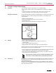
Part-turn actuators SG 05.1 – SG 12.1 / SGR 05.1 – SGR 12.1 AUMA NORM Operation instructions 14. Setting the torque switching .. 14.1 Setting The set torque must suit the valve! This setting must only be changed with the consent of the valve manufacturer! Figure L: Torque switching heads Setting OPEN Setting CLOSED Ft. Lbs Ft. Lbs O O .. . 80 90 100 P 0 11 70 11 0 O 10 0 90 80 70 Loosen both lock screws O at the torque dial (figure L).
Part-turn actuators SG 05.1 – SG 12.1 / SGR 05.1 – SGR 12.1 AUMA NORM Operation instructions 15. Test run 15.1 Checking the direction of rotation . Place indicator disc on shaft. The direction of rotation of the indicator disc (figure M) indicates the direction of rotation of the output drive. Figure M: Indicator disc OPEN . . CLOSED Move actuator manually to intermediate position or to sufficient distance from end position.
Part-turn actuators SG 05.1 – SG 12.1 / SGR 05.1 – SGR 12.1 AUMA NORM Operation instructions 16. Setting the potentiometer (option) — For remote indication — .. . . . Move valve to end position CLOSED. Pull off indicator disc. Turn potentiometer (E2) counterclockwise until stop is felt. End position CLOSED corresponds to 0 %, end position OPEN to 100 %. Turn potentiometer (E2) back a little.
Operation instructions Part-turn actuators SG 05.1 – SG 12.1 / SGR 05.1 – SGR 12.1 AUMA NORM 17. Setting the electronic position transmitter RWG (option) — For remote indication or external control — After mounting the part-turn actuator to the valve, check setting by measuring the output current (see sections 17.1 or 17.2) and re-adjust, if necessary. Table 5: Technical data RWG 4020 KMS TP_ _ 4 / _ _ _ Terminal plans Output current Power supply Max. input current Max.
Part-turn actuators SG 05.1 – SG 12.1 / SGR 05.1 – SGR 12.1 AUMA NORM Operation instructions 17.1 Setting 2-wire system 4 – 20 mA and 3- /4-wire system 0 – 20 mA .. .. .. Connect voltage to electronic position transmitter. Move valve to end position CLOSED. Pulling off the indicator disc. Connect ammeter for 0 – 20 mA to measuring points (figure P-2). The circuit (external load) must be connected (observe max.
Part-turn actuators SG 05.1 – SG 12.1 / SGR 05.1 – SGR 12.1 AUMA NORM Operation instructions .. .. 17.2 Setting 3-/4- wire system 4 – 20 mA Connect voltage to electronic position transmitter. Move valve to end position CLOSED. Pull off indicator disc. Connect ammeter for 0 – 20 mA to measuring points (figure P-3). .. The circuit (external load) must be connected (observe max.
Part-turn actuators SG 05.1 – SG 12.1 / SGR 05.1 – SGR 12.1 AUMA NORM Operation instructions 18. Setting the mechanical position indicator .. . .. Place indicator disc on shaft. Move valve to end position CLOSED. Turn lower indicator disc (figure Q-1) until symbol CLOSED is in alignment with the mark on the cover (figure Q-2). Move actuator to end position OPEN. Hold lower indicator disc in position and turn upper disc with symbol OPEN until it is in alignment with the mark on the cover.
Part-turn actuators SG 05.1 – SG 12.1 / SGR 05.1 – SGR 12.1 AUMA NORM Operation instructions 20. Setting the operating time For part-turn actuators with 1-phase AC motors, the operating time can be adjusted. .. .. .. Work on the electrical system or equipment must only be carried out by a skilled electrician himself or by specially instructed personnel under the control and supervision of such an electrician and in accordance with the applicable electrical engineering rules.
Part-turn actuators SG 05.1 – SG 12.1 / SGR 05.1 – SGR 12.1 AUMA NORM Operation instructions 21. Enclosure protection IP 68 (option) Definition According to EN 60 259, the conditions for meeting the requirements of enclosure protection IP 68 are to be agreed between manufacturer and user. AUMA actuators and controls in enclosure protection IP 68 meet the following requirements according to AUMA: Duration of submersion in water max. 72 hours Head of water max.
Part-turn actuators SG 05.1 – SG 12.1 / SGR 05.1 – SGR 12.1 AUMA NORM Operation instructions 22. Maintenance After maintenance, check part-turn actuator for damage to paint finish. If damage to paint-finish has occurred after mounting, it has to be touched up to avoid corrosion. Original paint in small quantities can be supplied by AUMA. AUMA part-turn actuators require very little maintenance. Precondition for reliable service is correct commissioning.
Part-turn actuators SG 05.1 – SG 12.1 / SGR 05.1 – SGR 12.1 AUMA NORM Operation instructions 24. Disposal and recycling AUMA actuators have an extremely long lifetime. However, they have to be replaced at one point in time. The actuators have a modular design and may therefore easily be disassembled, separated, and sorted according to materials, i.e.: .. .. . . . electronic scrap various metals plastics greases and oils The following generally applies: Collect greases and oils during disassembly.
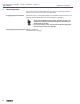
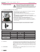
16 10.0 S1/S2 S1 / S2 AUMA ACTUATORS INC. PITTSBURGH PA USA SG 07.1-F7 Com. No.:1309533 No: 3302MD 19302 n: 11 rpm T open: 120-300Nm T close 120-300Nm Lubr.: F1 153.2 153.0 2.4 2.0 38.2.3 38.2.2 38.0 38.2.4 153.3 153.1 5.0 21.0 S2 36.10 S1 / S2 - Actuator type - Commission number - Works number - Enclosure protection/ output speed Torque range in CLOSED / OPEN - Lubricant - Temperature range 39.2.4 39.2 39.2.2 39.2.3 Sample name plate S1 / S2 39.0 152.1 152.
Part-turn actuators SG 05.1 – SG 12.1 / SGR 05.1 – SGR 12.1 AUMA NORM Operation instructions Note: Please state type and commission no. of the actuator (see name plate) when ordering spare parts. Delivered spare parts may slightly vary from the representation in these instructions. No. Type Designation 1 2.0 2.4 3.0 4.0 5.0 10.0 14 16 17.0 21.0 29.0 32.0 34.0 E B E B B B B E E B B B B B 34.22 B 34.23 34.24 34.7 34.8 34.9 35.0 36.0 36.1 36.2 36.3.1 B B B B B B B B B B 36.3.
Part-turn actuators SG 05.1 – SG 12.1 / SGR 05.1 – SGR 12.
North American Sales and Service: US Headquarters and Factory: AUMA Actuators, Inc. 100 Southpointe Blvd. Canonsburg PA 15317 Tel: 724-743-AUMA (2862) Fax: 724-743-4711 email: mailbox@auma-usa.com www.auma-usa.