
User guide

17.2 Setting 3-/4- wire system 4 – 20 mA
.
Connect voltage to electronic position transmitter.
.
Move valve to end position CLOSED.
.
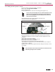
Pull off indicator disc.
.
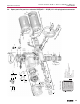
Connect ammeter for 0 – 20 mA to measuring points (figure P-3).
The circuit (external load) must be connected (observe max.
load R
B
), or the appropriate connections at the terminals
(refer to wiring diagram) must be jumpered, otherwise no
value can be measured.
.
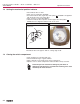
Turn potentiometer (E2) counterclockwise until stop is felt.
.
Turn potentiometer (E2) slightly back.
.
Turn potentiometer “0” clockwise until output current starts to increase.
.
Turn back potentiometer “0” until a residual current of approx. 0.1 mA is
reached.
.
Move valve to end position OPEN.
.
Set potentiometer “max.” to end value 16 mA.
.
Move valve to end position CLOSED.
.
Set potentiometer “0” from 0.1 mA to initial value 4 mA.
This results in a simultaneous shift of the end value by 4 mA, so that the
range is now 4 – 20 mA.
.
Approach both end positions again and check setting. If necessary, correct
the setting.
If the maximum value cannot be reached, the selection of the
reduction g
earing must be checked.
23
Part-turn actuators SG 05.1 – SG 12.1 / SGR 05.1 – SGR 12.1
Operation instructions AUMA NORM
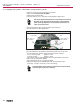
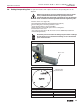
Figure P-3
“0” (0/4 mA)
“max.” (20 mA)
Meas. point (+)
0/4 – 20 mA
Meas. point (–)
0/4 – 20 mA
Cover plate
E2