AURORA Inverters INSTALLATION AND OPERATOR’S MANUAL Model number: PVI-3600-OUTD-UK-F-W Rev. 1.
Installation and Operator’s Manual (PVI-3600-OUTD-UK-F-W Rev.: 1.0) Page 2 of 63 REVISION TABLE Document Revision Author Date Change Description 1.0 T. Melzl 5/1/2006 First release of the document 1.1 T.Melzl 5/3/2006 Updated Anti-Inlanding reference SAVE THESE INSTRUCTIONS ! IMPORTANT SAFETY INSTRUCTIONS MAGNETEK: Reproduction and disclosure, even partially, of the contents of this manual are strictly forbidden without prior authorization of Magnetek.
Installation and Operator’s Manual (PVI-3600-OUTD-UK-F-W Rev.: 1.0) Page 3 of 63 IMPORTANT SAFETY INSTRUCTIONS This manual contains important safety and operational instructions that must be accurately understood and followed during the installation and maintenance of the equipment.
Installation and Operator’s Manual (PVI-3600-OUTD-UK-F-W Rev.: 1.0) Page 4 of 63 USEFUL INFORMATION AND SAFETY STANDARD FOREWORD The installation of AURORA must be performed in full compliance with national and local standards and regulations AURORA has no internal user serviceable parts other than fuses. For any maintenance or repair please contact the nearest authorized repair center. Please contact your reseller if you need to know the nearest authorized repair center.
Installation and Operator’s Manual (PVI-3600-OUTD-UK-F-W Rev.: 1.0) Page 5 of 63 In particular, during transport and handling, parts shall not be bent and/or the insulation distances shall not be changed. There should be no contact between electronic parts and connection terminals. Electrical parts must not be mechanically damaged or destroyed (potential health risk). ELECTRICAL CONNECTION With the inverter powered, comply with all prevailing national regulations on accidents prevention.
Installation and Operator’s Manual (PVI-3600-OUTD-UK-F-W Rev.: 1.0) Page 6 of 63 PVI-3600-OUTD-UK-F-W This document applies to the above-mentioned inverters, only. Fig.
Installation and Operator’s Manual (PVI-3600-OUTD-UK-F-W Rev.: 1.0) Page 7 of 63 CONTENTS: 1 FOREWORD 1.1 WIND ENERGY 2 SYSTEM DESCRIPTION 2.1 Main Elements of a Wind System: 2.2 Data Transmission and Check 2.3 AURORA Technical Description 2.4 Protective Devices 2.4.1 Anti-Islanding 2.4.2 Ground Fault 2.4.3 Further Protective Devices 2.5 System Design: 3 INSTALLATION 3.1 Package Inspection 3.2 Package Check List 3.3 Choosing Installation Location 3.4 Wall Mounting 3.
Installation and Operator’s Manual (PVI-3600-OUTD-UK-F-W Rev.: 1.0) 8.2 8.3 8.4 8.
Installation and Operator’s Manual (PVI-3600-OUTD-UK-F-W Rev.: 1.0) 1 Page 9 of 63 FOREWORD This document contains a technical description of the AURORA wind inverter so as to provide the installer and user all the necessary information about installation, operation and use of AURORA. 1.1 WIND ENERGY Industrialized countries (greater energy consumers) have been experimenting with energy-saving methods and reducing pollutant levels.
Installation and Operator’s Manual (PVI-3600-OUTD-UK-F-W Rev.: 1.0) 2.1 Page 10 of 63 Main Elements of a Wind System: A wind system is composed of a wind turbine, a permanent magnet generator or alternator, Wind Interface Box and Aurora Wind inverter. The output of wind turbine is converted from mechanical energy into electrical energy by the permanent magnet (PM) generator. The output of the PM generator is a variable frequency, variable voltage waveform, commonly referred to as “wild AC”.
Installation and Operator’s Manual (PVI-3600-OUTD-UK-F-W Rev.: 1.0) Page 11 of 63 The Aurora Wind Inverter is designed to accept only a single wind input. The current of this input is limited to 20 Amperes. Safety Brake Wind Interface Box Diversion Load Fig.
Installation and Operator’s Manual (PVI-3600-OUTD-UK-F-W Rev.: 1.0) 2.2 Page 12 of 63 Data Transmission and Check In case multiple inverters are used, they can be monitored remotely by using an advanced communication system based on the serial interface RS485 or on the Power Line Modem (PLM) technology. For further information, refer to the corresponding sections of this manual. 2.3 AURORA Technical Description Figure 4 shows a block diagram of AURORA.
Installation and Operator’s Manual (PVI-3600-OUTD-UK-F-W Rev.: 1.0) Page 13 of 63 Aurora Wind Inverter 20 A Aurora Wind Inteface Box DC/DC Boost Converter High Voltage DC Bus Grid Interface Inverter CB1 K1 PMSG Line Filter PMG input Voc = 400 V max. Vnom = 360 V nom. Vmin = 40 3.6 kW 3.
Installation and Operator’s Manual (PVI-3600-OUTD-UK-F-W Rev.: 1.0) Page 14 of 63 This process ensures optimal performance levels of the whole unit, as well as a high efficiency over the input voltage operating range and load conditions, always in full compliance with the applicable directives, standards and regulations. 2.4 2.4.
Installation and Operator’s Manual (PVI-3600-OUTD-UK-F-W Rev.: 1.0) Page 15 of 63 Control of the internal temperatures to automatically drive the speed of the external cooling fan. This will allow the inverter to deliver the maximum output power for ambient temperatures up +40 ° C . The AURORA is designed for safe and reliable operation. This is made possible by the use of redundant control circuits. 2.
Installation and Operator’s Manual (PVI-3600-OUTD-UK-F-W Rev.: 1.0) Page 16 of 63 WARNING: The connection of AURORA to the electrical distribution grid must be performed only after receiving authorization from the utility that operates the grid. 3.1 Package Inspection NOTE: The distributor presented your AURORA WIND Inverter to the delivering carrier securely packed and in perfect condition.
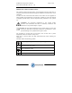
Installation and Operator’s Manual (PVI-3600-OUTD-UK-F-W Rev.: 1.0) 3.2 Page 17 of 63 Package Check List Description Wind Inverter Bag with 4 screws, 4 blocks and 1 Tap wrench Torx TX20 One mounting reference drawing One copy of this manual One certificate of warranty CD-Rom with communication software Quantity (No.
Installation and Operator’s Manual (PVI-3600-OUTD-UK-F-W Rev.: 1.0) 3.3 Page 18 of 63 Choosing Installation Location The location for the installation of AURORA should be selected in accordance to the following recommendations: AURORA should be placed at a suitable height from ground to allow easy reading of the front display and the status LEDs. Leave enough room around the unit to allow easy installation and maintenance.
Installation and Operator’s Manual (PVI-3600-OUTD-UK-F-W Rev.: 1.0) 3.4 Page 19 of 63 Wall Mounting AURORA should be mounted in a vertical position as shown in figure 7. NOTE: AURORA ratings are based on a vertical mounting position. Although it is possible to mount AURORA in a tilted position, the thermal performance in that case may be de-rated. In any case avoid mounting AURORA with the front plate rotated, always make sure that the fins of the front heat-sink are vertical.
Installation and Operator’s Manual (PVI-3600-OUTD-UK-F-W Rev.: 1.0) Page 20 of 63 Install the expansion screws in the wall so that the head of the screws is about 4mm from the wall surface. Then hang AURORA on the wall by fitting the screw heads in the mounting slots as shown in Fig.7, and secure the screws. Fig.7 AURORA wall mounting It is possible to mount AURORA in a tilted position.
Installation and Operator’s Manual (PVI-3600-OUTD-UK-F-W Rev.: 1.0) Page 21 of 63 higher than + 40 °C an output power de-rating may occur on the top units. RECOMMENDED ASSEMBLING Fig.8 Recommended multi Aurora mounting It is recommended that the unit be placed out of direct sunlight. WARNING: During operation, inverter surface can reach very high temperatures. DO NOT touch inverter surface to prevent the risk of burns. 0 - 45° Derating NO Derating Derating 45° Derating Fig.
Installation and Operator’s Manual (PVI-3600-OUTD-UK-F-W Rev.: 1.0) 3.5 Page 22 of 63 Preliminaries to Electrical Connections WARNING: The electrical connections can be done only after AURORA is firmly mounted to the wall. WARNING: The connection of AURORA to the electrical distribution grid must be performed only by skilled operators and after having received authorization from the utility that operates the grid.
Installation and Operator’s Manual (PVI-3600-OUTD-UK-F-W Rev.: 1.0) Page 23 of 63 AURORA to the grid. Recommended ratings for the Ac over-current protection device is maximum 20A, 240V. Diversion Load Wind Turbine Safety Brake Switch Wind Interface Box A u r o r a Grid AC Disconnect Load Center Wire in accordance with NEC and applicable local codes Fig.
Installation and Operator’s Manual (PVI-3600-OUTD-UK-F-W Rev.: 1.0) Page 24 of 63 WARNING: All power wires connecting to AURORA inverter must have a section of at least 14 AWG (2.5mm2) and must be able to operate at temperature of at least 90 °C. All wiring must be sized in accordance with the National electrical standards and applicable local codes. The wire size may need to be increased due to temperature, wire length and conduit fill factors.
Installation and Operator’s Manual (PVI-3600-OUTD-UK-F-W Rev.: 1.0) Page 25 of 63 WARNING: Use listed watertight conduit connectors to maintain the enclosure rating of the AURORA inverter. To access the wiring terminal strip inside of the AURORA inverter remove the side panel as shown in Fig.12. Removing the panel allows you to access the screw terminal blocks and the conduit access holes. Fig.12: Removing the side panel WARNING: To avoid the risk of electric shock from energy stored in capacitors.
Installation and Operator’s Manual (PVI-3600-OUTD-UK-F-W Rev.: 1.0) Page 26 of 63 The conduit and the wire lengths depend on the distance between the unit and Ac disconnect and the Wind Interface Box. The wires must be inserted in the conduits and routed to the terminal blocks. Pay careful attention in bending the cables properly. The insulation at the end of the cable should be stripped back ½ “ (14mm). The maximum wire size that the terminal will accept is 10AWG.
Installation and Operator’s Manual (PVI-3600-OUTD-UK-F-W Rev.: 1.0) Page 27 of 63 Step 1/7: Open the Ac disconnect switch or circuit breaker and lockout the Ac disconnecting means. Step 2/7: Open the Dc disconnect switch and lockout the Dc disconnecting means. Step 3/7: Verify there is no voltage on the connection terminals. Step 4/7: Connect AURORA to the Main Ground (Protective Earth) The input and output circuits are isolated from the enclosure.
Installation and Operator’s Manual (PVI-3600-OUTD-UK-F-W Rev.: 1.0) Page 28 of 63 Step 5/7: Connect AURORA to the Ac disconnect switch or circuit breaker WARNING: Use proper, low impedance cables to connect AURORA to the Ac disconnect or circuit breaker, and between the disconnecting means to the grid. To ensure proper operation the impedance seen at the Ac output terminals of AURORA must be below 1ohm.
Page 29 of 63 PV INPUT 1 -IN1 -IN1 +IN1 +IN1 PV INPUT 2 -IN2 -IN2 +IN2 +IN2 Installation and Operator’s Manual (PVI-3600-OUTD-UK-F-W Rev.: 1.0) + - Fig.14: Wind Input with the two input sections paralleled NOTE: Paralleling the two input sections, the input current rating becomes equivalent to 20A (24A short circuit). In the parallel mode configuration the maximum input power limit is equivalent to the max output power plus losses. It can be rated to 3800W.
Installation and Operator’s Manual (PVI-3600-OUTD-UK-F-W Rev.: 1.0) Page 30 of 63 2) Install suitable watertight connectors to the AURORA enclosure 3) Terminate the wires labeled + and – in the same input section terminal blocks of AURORA Input 1. 4) Connect the cable + to the terminal block labeled + 5) Connect the cable – to the terminal block labeled – 6) Tighten the screw to a torque of 0.6Nm (5.3 in-lbs.) 7) Make the proper connections of the cables to the Wind Interface Box.
Installation and Operator’s Manual (PVI-3600-OUTD-UK-F-W Rev.: 1.0) 4 Page 31 of 63 START-UP NOTE: do not lay any object on AURORA during operation. WARNING: do not touch the heat sink during operation, some parts could be very hot and cause serious burns. To turn on AURORA by turning ON the AC disconnecting means after allowing the wind turbine to turn.
Installation and Operator’s Manual (PVI-3600-OUTD-UK-F-W Rev.: 1.0) 5 5.1 Page 32 of 63 MONITORING AND DATA TRANSMISSION User’s Interface Mode WARNING: RS-485 cable must be UL/CSA certified wiring and must be additionally protected by means of a non-metallic tubing. The AURORA inverter usually works automatically and is maintenance-free.
Installation and Operator’s Manual (PVI-3600-OUTD-UK-F-W Rev.: 1.0) Fig.
Installation and Operator’s Manual (PVI-3600-OUTD-UK-F-W Rev.: 1.0) 5.2 Page 34 of 63 Available Data AURORA provides two sets of data that are accessed using AURORA interface software. 5.2.1 Real time data The real time operating data can be transmitted on request over the communication lines and is not recorded internally by the AURORA inverter. The AURORA interface software can be used to retrieve and store data on a PC computer.
Installation and Operator’s Manual (PVI-3600-OUTD-UK-F-W Rev.: 1.0) Page 35 of 63 All data are available for transmission via the RS-485 link or PLM. In addition, the first two data of the list are displayed on the LCD. The AURORA Communicator software shall be used in order to download the internally stored data. 5.3 LED Indicators On the front panel of the AURORA inverter there are three LEDs, which give status indications: 1. A green LED labeled Power 2. A yellow LED labeled FAULT 3.
Installation and Operator’s Manual (PVI-3600-OUTD-UK-F-W Rev.: 1.0) LEDs Status Operational Status Page 36 of 63 Remarks Power (Green): Fault (Yellow): GFI (Red): AURORA self-disconnection during no or low wind conditions. Input voltage below 50 Vdc on the MPPT input Power (Green): Fault (Yellow): GFI (Red): AURORA initialization, settings loading and waiting for grid check Input voltage above 50 Vdc for the MPPT input . It is a transition status while operating conditions are checked.
Installation and Operator’s Manual (PVI-3600-OUTD-UK-F-W Rev.: 1.0) Page 37 of 63 G Y R 1) Sleep Mode AURORA is in the disconnection phase; this happens whenever the input power is too low to export power to the feed grid and power the inverter control system as well. G Y R 2) AURORA Initialization and Grid Check The unit is in the initialization phase: energy supply for the inverter control system is high enough.
Installation and Operator’s Manual (PVI-3600-OUTD-UK-F-W Rev.: 1.0) Page 38 of 63 reset, there could be a water seepage due to condensation that is causing a ground fault or there is some other insulation breakdown. Have the system inspected by qualified personnel. If the signal cannot be reset, insulate AURORA on both Dc and Ac sides so as to reach a safe condition; then contact an authorized center for repairing the fault.
Installation and Operator’s Manual (PVI-3600-OUTD-UK-F-W Rev.: 1.
Installation and Operator’s Manual (PVI-3600-OUTD-UK-F-W Rev.: 1.0) 5.5 Page 40 of 63 LCD Display The 2-line LCD display is located on the front panel and shows: the status of the inverter and statistical data; service messages for the operator; messages of faults or damages found. Data are shown cyclically, the screens change every 5 seconds. On the right of the display there is a button that when pressed freezes the screen. Pushing the button again unfreezes the screen.
Installation and Operator’s Manual (PVI-3600-OUTD-UK-F-W Rev.: 1.
Installation and Operator’s Manual (PVI-3600-OUTD-UK-F-W Rev.: 1.0) Page 42 of 63 Fourth screen: Output power and Voltage Input Pac Vin ## W ## V Fifth screen: Total energy exported to the grid and total operating time (that is time during which the unit was active). Both data are measured since the unit was first operated.
Installation and Operator’s Manual (PVI-3600-OUTD-UK-F-W Rev.: 1.0) Page 43 of 63 Sixth screen: Time during which the unit exported energy to the grid, and number of times that unit connected to the grid. Timegrid hh:mm:ss Numgrid ## Seventh screen: Daily energy and mode of operation of the inverter E-Today ## Wh ModeInverter OK In case the inverter is not working properly the Fault or Ground Fault LEDs will turn on as described in paragraph 5.
Installation and Operator’s Manual (PVI-3600-OUTD-UK-F-W Rev.: 1.0) Page 44 of 63 This screen shows the code of the error found, for further information refer to chapter 5.4.
Installation and Operator’s Manual (PVI-3600-OUTD-UK-F-W Rev.: 1.0) Page 45 of 63 The sequence of the screens is summarized in the following figure: Grid fail Initializing...
Installation and Operator’s Manual (PVI-3600-OUTD-UK-F-W Rev.: 1.
Installation and Operator’s Manual (PVI-3600-OUTD-UK-F-W Rev.: 1.0) 6 6.1 Page 47 of 63 DATA CHECK AND COMMUNICATION RS-485 serial link The RS-485 link uses two wires for signals plus a third wire for signal grounding, which is different from the equipment grounding of the unit. The wires must be run in a watertight conduit through the bottom of the unit as explained in paragraph 3.5 after removing the watertight cap and installing a suitable watertight conduit connector.
Installation and Operator’s Manual (PVI-3600-OUTD-UK-F-W Rev.: 1.0) Page 48 of 63 from OFF to ON. The default position of the switch is OFF. Also, each unit must have a different address. See par. 6.3 to change the addresses. In order for the RS485 communication line to perform the best, Magnetek recommends to connect its PVI-RS232485 adapter before the first unit of the daisy-chain (see fig.
Installation and Operator’s Manual (PVI-3600-OUTD-UK-F-W Rev.: 1.0) 6.2 Page 49 of 63 Power Line Modem (PLM) A PLM modem card is an available option card for the Aurora. To collect the data transmitted over the PLM link two options are available: • Use the AURORA Easy Control data logger, model number PVI-AEC (*Check on availability in 2007).
Installation and Operator’s Manual (PVI-3600-OUTD-UK-F-W Rev.: 1.0) Page 50 of 63 NOTE: the maximum number of inverters that can be connected via PLM is 63.NOTE: It is not possible to have more than one receiving device such as AURORA Easy Control data logger or AURORA PLM/RS232 interface box connected to the same power line. Fig.
Installation and Operator’s Manual (PVI-3600-OUTD-UK-F-W Rev.: 1.0) 6.3 Page 51 of 63 Display menù When using PLM or the RS-485 serial link communication each unit must have a unique address. The default address of each unit is 2. When connecting multiple units on the same serial or PLM link a new address needs to be assigned to each unit to avoid communication errors. 6.4 Address Information Addresses 0 is reserved for the host computers; addresses 1 is reserved for the automatic addressing mode.
Installation and Operator’s Manual (PVI-3600-OUTD-UK-F-W Rev.: 1.0) Page 52 of 63 2 3 … 63. AUTO 4) Confirm the choice by pressing once more the key for at least 5 seconds. NOTE: When using RS-485 link there can be no more than 31 inverters connected on the same link. Although you are free to choose any address between 2 and 63 it is recommended that you use addresses between 2 and 33 for the RS-485 serial link.
Installation and Operator’s Manual (PVI-3600-OUTD-UK-F-W Rev.: 1.0) Page 53 of 63 2) Verify that the inverter is set in mode Parallel: - SET IN MODE PARALLEL A short touch of the key allows to scroll the two options. In order to confirm the selection, press for longer than 5 sec. the same key. Press it for a shorter time to come back to the previous display.
Installation and Operator’s Manual (PVI-3600-OUTD-UK-F-W Rev.: 1.0) Page 54 of 63 6) Press the key for longer than 5 sec. to confirm the chosen BAUD RATE shown on the display. Press it for a shorter time to come back to the previous display. NOTE: Generally the standard speed to be chosen is 19200 Baud. Only in presence of particularly long or noisy lines a lower speed is recommended. 6.8 Measurement Accuracy All measurement device have errors.
Installation and Operator’s Manual (PVI-3600-OUTD-UK-F-W Rev.: 1.0) Page 55 of 63 Resolution Data Accuracy Display Measurement Vin1 1V 600mV 2% Vin2 1V 600mV 2% Iin1 0.1A 15mA 2% Iin2 0.
Installation and Operator’s Manual (PVI-3600-OUTD-UK-F-W Rev.: 1.0) 7 Page 56 of 63 TROUBLESHOOTING AURORA inverters comply with standards set for grid-tied operation, safety and electromagnetic compatibility. Before being delivered by Magnetek, the product has been successfully subjected to several tests to check: operation, protective devices, performance and durability. All these tests, together with the system ensuring Magnetek quality, guarantee AURORA optimal operation.
Installation and Operator’s Manual (PVI-3600-OUTD-UK-F-W Rev.: 1.0) Page 57 of 63 Before contacting the service center, keep the following information handy: INFO AURORA NOTE: Information to be found directly on LCD AURORA model? Serial number? Week of production? LED flashing? Light blinking or steady? Signal displayed? Observed wind speed during the malfunction. There is a minimum wind speed that is needed in order to product enough energy to supply the inverter controls.
Installation and Operator’s Manual (PVI-3600-OUTD-UK-F-W Rev.: 1.0) 8 8.1 Page 58 of 63 TECHNICAL FEATURES Input Values WARNING: The Wind turbine maximum output voltage must be less than 600Vdc in under any condition.
Installation and Operator’s Manual (PVI-3600-OUTD-UK-F-W Rev.: 1.0) Description Nominal input voltage Minimum input voltage to connect to the grid “Absolute Maximum Rating” for input voltage Input voltage, MPPT operating range Input voltage, MPPT range at full power Max. operating input current (Wind MPPT Input) Max.
Installation and Operator’s Manual (PVI-3600-OUTD-UK-F-W Rev.: 1.0) 8.2 Page 60 of 63 Output Values Description Value PVI-3600-OUTD-UK-F-W Nominal output power 3600 W Grid voltage, nominal operating values 230Vac Grid voltage, operating ranges Grid frequency, maximum range Grid frequency, nominal Grid frequency, operating range 207 to 264Vac 47 to 63 Hz 50 Hz 47 to 50.5 Hz Nominal output current 16 Arms Output over current protection 20 Arms 8.
Installation and Operator’s Manual (PVI-3600-OUTD-UK-F-W Rev.: 1.0) 8.4 Page 61 of 63 General characteristics Description Maximum efficiency Internal consumption during stand-by Internal consumption during night time Operating ambient temperature Enclosure type Relative Humidity Audible Noise Size (height x width x depth): Weight Value PVI-3600-OUTD-UK-F-W 96% <8W < 0,30 W -25°C to +60°C (-13°F to 140°F) Nema 4X 0 – 100 % condensing < 40dBA 420 x 310 x 144 mm 12.
Installation and Operator’s Manual (PVI-3600-OUTD-UK-F-W Rev.: 1.0) 8.5 Page 62 of 63 Power Derating To ensure inverter safe operation under any temperature and electrical condition, the unit will automatically derate the power to be delivered to the grid.
Installation and Operator’s Manual (PVI-3600-OUTD-UK-F-W Rev.: 1.0) Page 63 of 63 The above cases, originating a power derating, can also occur at the same time, but the power derating will always correspond to the lowest value read.