
User manual


~ 6 ~
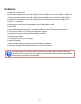
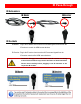
Front View — Receiving Unit ASP-CATX1RS-RX
9. RS-232: Connect to PC serial port with a DSUB-9 male-male cable here
10. Signal Level: Adjust the 8-level equalization control to the received HDMI signals. The HDMI signal
level varies from MAX (strongest) to MIN (weakest) for respective transmission length from longest
possible range to short distance. Please adjust the signal level from MIN to MAX and stop turning the
rotary switch whenever the audio/video is playing normally. Inappropriate signal level setting may
cause overpowering issue that would shorten the product life significantly!
11. Dip Switch: Setup the RS-232 mode for serial communication channel
12. HDMI OUT: Connect to a HDMI display with a HDMI male-male cable.
13. IR Receiver: Infrared 3.5mm socket for plugging in the extension cable of IR receiver
14. IR Blaster: Infrared 3.5mm socket for plugging in the extension cable of IR blaster
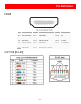
Rear View — Receiving Unit ASP-CATX1RS-RX
15. +5V DC: Connect to 5V DC power supply.
16. HDMI Signal IN: Plug in a Cat-5/5e/6 cable to be linked to the receiving unit ASP-CATX1RS-RX.
DIP Switch Position
Description
TX & RX
ON [
]
TxD: The 2
nd
pin of RS-232, which is in charge of receiving data
RxD: The 3
rd
pin of RS-232, which is in charge of sending data
OFF [
]
TxD: The 3
rd
pin of RS-232, which is in charge of receiving data
RxD: The 2
nd
pin of RS-232, which is in charge of sending data